
Plastic Guide Pulley: Molding and Bearing Assembly
A plastic guide pulley for an automation conveyor was manufactured as a molded wheel, followed by installation of a purchased bearing. The project needed dimensional control across four cavities and a defined check of the completed assembly's rotation behavior.
The owner-confirmed record includes 50 T1 dimensional specimens, a 10-specimen running-torque check and a separately scoped pilot balance sample. Cumulative deliveries reached 18,000 pieces through September 2026.
Process
Four-cavity molding
Running Torque
10 specimens · 60 rpm
Your Application
Custom plastic pulleys
Project Overview
A molded wheel and a separately installed bearing
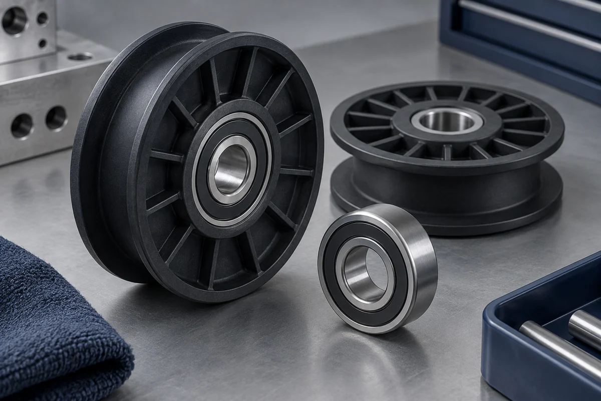
The component provides a polymer running surface around a 6202 bearing in a conveyor guide arrangement. Its material is a PA66-based wear-modified compound prepared for the project, not a supplier's standard finished grade. No generic friction coefficient or temperature rating is transferred from a base-resin data sheet.
The manufacturing route is four-cavity injection molding followed by bearing press-assembly. The bearing is installed after the plastic wheel is molded; it is not placed in the injection mold. There is no second overmolding shot in the confirmed process.
FECISION's scope covered DFM, molding and assembly review, and component inspection, with mold manufacture assigned to an anonymous partner. The owner confirmed mass-production supply and 18,000 cumulative deliveries through September 2026. This delivery quantity is not the population used for each validation test.
Confirmed project scope
| Application | Guide pulley in an automation conveyor assembly |
|---|---|
| Material | PA66-based wear-modified compound; project-specific formulation |
| Manufacturing route | Four-cavity injection molding followed by 6202 bearing press-assembly |
| Component envelope | 40 mm nominal wheel outside diameter; 35 mm bearing outside diameter |
| Project roles | FECISION: DFM, molding and assembly review, component inspection; partner: mold manufacture |
| T1 dimensional population | 50 parts, all four cavities represented |
| Production status | 18,000 pieces delivered cumulatively through September 2026 |
Manufacturing Challenge
Connect molded geometry with the bearing assembly
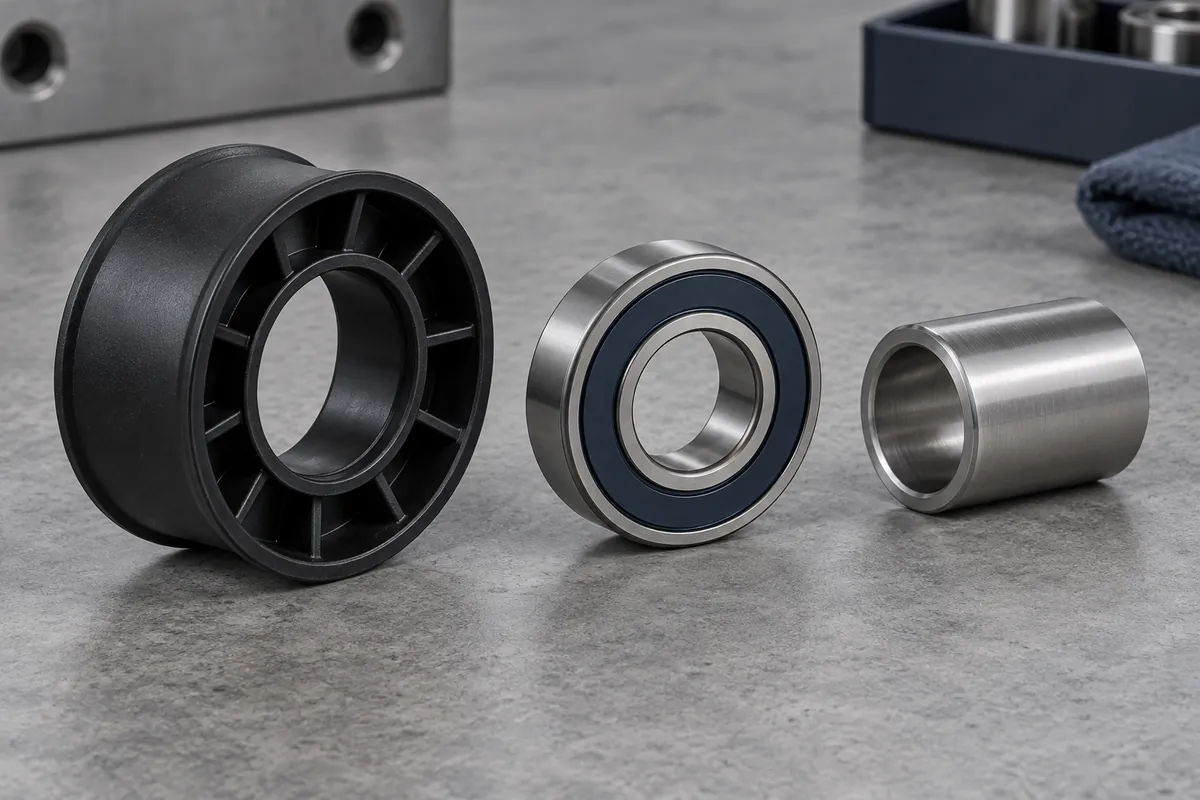
The relevant relationship is between the molded bearing seat, the running surface and the installed bearing. Measuring the wheel outside diameter alone does not establish the behavior of the completed assembly. The project therefore kept dimensional inspection and rotation checks as separate acceptance activities.
The owner clarified a nominal 40 mm wheel outside diameter and a 35 mm bearing outside diameter. The specified tread wall of 2 ± 0.2 mm refers to the radial region between an approximately 36 mm hub outside diameter and the 40 mm running surface. It does not describe the entire radial distance from the bearing to the wheel outside.
These dimensions describe this component only. They are not a recommended fit or minimum wall for another bearing, compound or load. A different design needs its own drawing, retention and assembled-function review.
Trial and Assembly Review
Separate cavity coverage from functional sampling
T1 comprised 50 molded parts, with approximately 12–13 from each of four cavities. All 50 underwent dimensional inspection of the bearing-seat bore and wheel outside diameter. That full trial inspection is distinct from the smaller sample used for a functional measurement after bearing installation.
The running-torque check used 10 assembled specimens covering all four cavities, with two or three specimens from each. The owner confirmed steady rotation at 60 rpm and a measured range of 0.02–0.04 N·m. The result describes continuous running torque, not the peak required to start from rest.
No breakaway-torque value is published because the supplied range does not measure that property. Nor is a percentage improvement calculated from the earlier trial summaries: the baseline methods and sample populations were not aligned sufficiently to support that comparison.
Recorded Results
Keep each result attached to its tested population
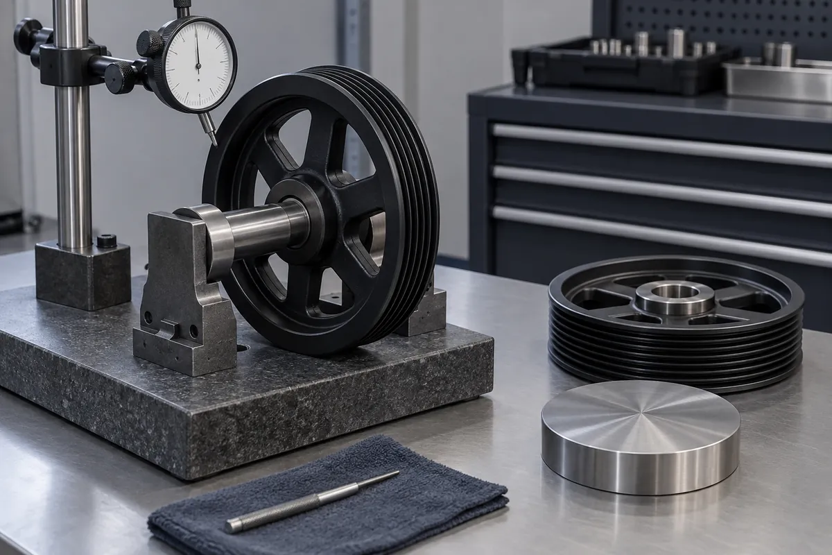
From the subsequent 200-part pilot, 10 specimens across the four cavities underwent a dynamic-balance check. The owner reported all 10 accepted against the recorded G6.3 criterion at 1,000 rpm. This is a sampled project result, not a claim that all 200 pilot parts or all delivered parts were balance tested.
The wear record separately describes three specimens evaluated against a steel counterface at 50 N and 1 m/s to an endpoint of 500 km, with a reported wear range of 0.06–0.09 mm. This limited test does not establish a guaranteed field life or transfer to a different mating surface.
| Check | Condition or feature | Reported observation | Population and scope |
|---|---|---|---|
| T1 dimensions | Wheel outside diameter and bearing-seat bore | All 50 T1 parts inspected | Four cavities, approximately 12–13 parts per cavity; not a capability index |
| Continuous running torque | 60 rpm after bearing installation | 0.02–0.04 N·m | 10 specimens across four cavities; not breakaway torque |
| Pilot dynamic balance | Recorded G6.3 criterion at 1,000 rpm | All 10 sampled specimens reported accepted | 10 from the 200-part pilot, across four cavities; not 100% production inspection |
| Wear evaluation | Steel counterface; 50 N; 1 m/s; 500 km endpoint | Reported wear range 0.06–0.09 mm | Three destructive specimens; not a rated service life |
The owner describes subsequent production balance sampling as five pieces per batch, not full inspection. The 1,000 rpm balance condition is not presented as a maximum operating-speed rating, and the sampled acceptance is not independent certification of the finished equipment.
Evidence Boundary
Carry the approved configuration forward
The case uses real project records supplied and confirmed by FECISION for anonymous publication. Original laboratory reports and project photographs are not reproduced here. Product design illustrations explain the component and inspection concepts; they are not evidence of the recorded measurements.
No supplier identity, base-resin performance claim, formal concentricity result or production defect-rate improvement is inferred from the available summary. Dimensional inspection, running torque, balance sampling and wear evaluation remain separate observations with different specimen counts.
For a new application, define the wheel, compound, bearing and mating component together, then agree the acceptance methods. A change in any of those inputs requires review before relying on the same manufacturing and validation evidence.
Related Guides
Plan the next pulley review
- Custom Plastic Pulleys: Prepare a Comparable RFQSpecify custom plastic pulleys with the belt interface, bearing, drawing datums, material and inspection scope before comparing molding quotations.
- Nylon vs Acetal Pulleys: Compare the Complete ApplicationCompare nylon and acetal pulley candidates through moisture, dimensional fit, contact conditions and wear tests, not a generic low-friction label.
- Plastic Pulley Bearings: Insert Mold or Assemble Later?Compare insert-molded and post-assembled pulley bearings through retention, molding exposure, press support, inspection and replacement requirements.
- Plastic Pulley Runout: Specify the Datum and Test SetupDefine radial and axial pulley runout with the correct datum, fixture, material condition and sample identity. Separate indicator sweep from concentricity.
- Plastic Pulley Grooves: Match the Belt, Cord and ContactReview plastic pulley groove and tread profiles with the mating belt or cord, clearance, alignment, molding details and application-specific acceptance.
- Plastic Pulley Wear Tests: Define Load, Speed and EvidenceBuild a pulley wear-test plan with controlled samples, counterface, load, speed, environment and measurements. Separate a test endpoint from rated life.
Review your wheel and bearing interface
Send the drawing, mating belt or track, bearing details and acceptance requirements for a defined manufacturing proposal.