
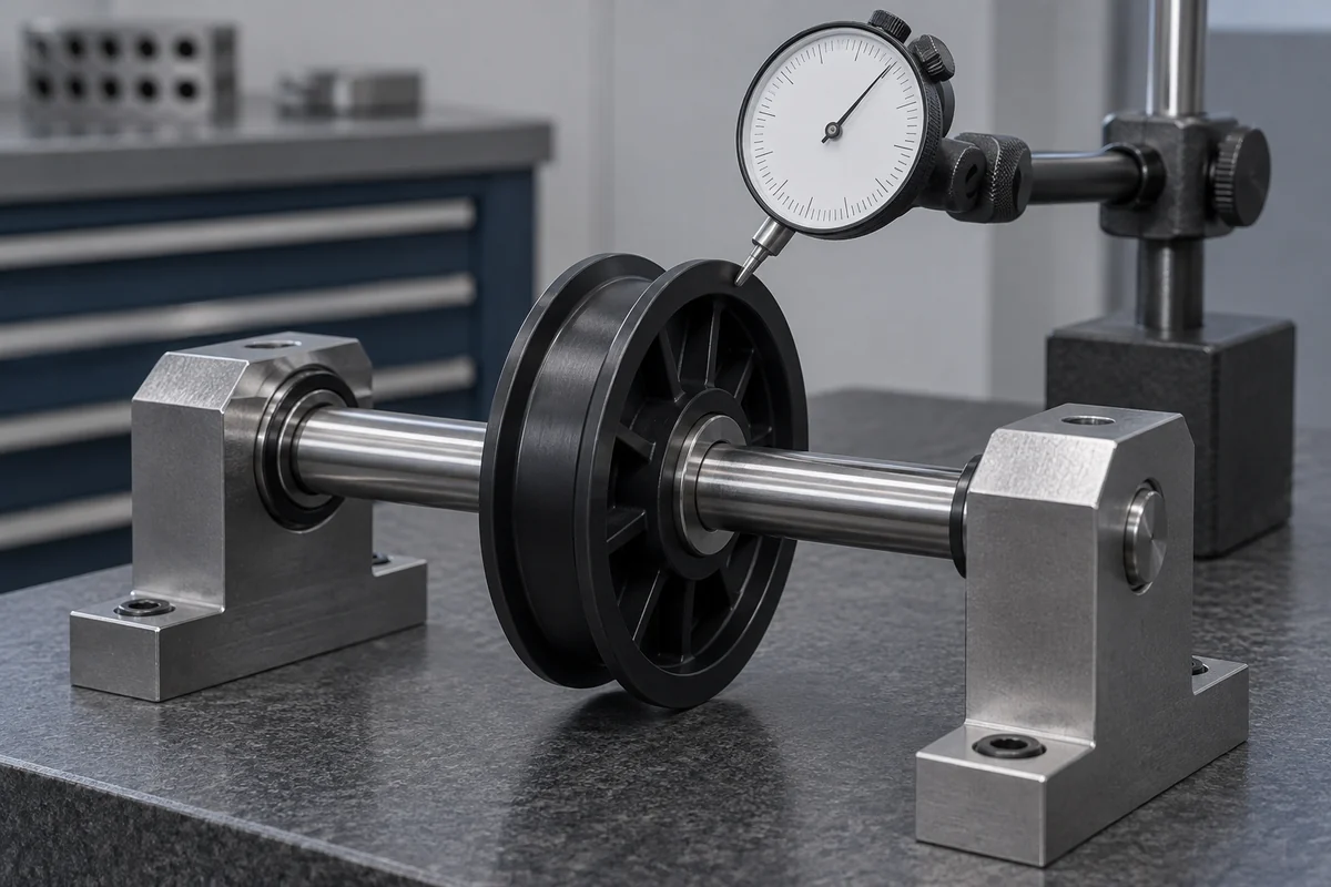
Product design illustrations. Final geometry, materials and acceptance criteria are project-specific.
A pulley can have an acceptable outside diameter and still run unevenly on its installed bearing. Diameter describes size; runout describes how a selected surface behaves as the part rotates about an established axis. When a drawing or report simply says “concentricity,” ask which geometric requirement and measurement method are actually intended before treating the result as acceptance evidence.
This distinction matters for injection-molded wheels because the bearing location, tread shape and side faces can respond differently to tool construction and processing. An indicator reading is useful, but only when its direction, contact location and support are controlled. The objective is a repeatable relationship to the functional axis, not an impressive number without a defined setup.
Identify the functional axis
Start with the installed assembly. Determine which bearing or bore establishes rotation and which surfaces carry the belt or track contact. Then connect the drawing's datum references to an inspection fixture. If the production shaft locates on the bearing inner ring, a test that locates only on a molded outside feature may answer a different question.
Inspecting a loose wheel on a mandrel and inspecting a completed bearing assembly can both be useful, but their results should remain distinct. The first may isolate molded geometry; the second includes the bearing and assembly relationship. Record the state tested rather than combining the readings into a single undifferentiated column on a report.
Separate radial and axial observations
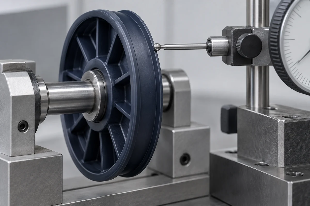
A radial indicator checks movement toward and away from the rotation axis at the specified tread location. An axial setup checks a side face in the direction of that axis. These readings are not interchangeable. State the contact track and whether a circular sweep at one location or a broader surface evaluation is required by the drawing.
For a grooved wheel, decide which feature is being inspected. Contact at a groove flank, bottom or flange may produce different readings and may need a different probe arrangement. Do not let the inspection department choose whichever surface is easiest to reach without checking its relationship to the function being controlled.
Document how the result is calculated. A total indicator variation over a rotation is not automatically a radius offset, and it should not be divided or renamed without the relevant geometric interpretation. If a drawing specifies a formal geometrical tolerance, use the applicable method and agreed standard rather than relabeling a convenient indicator sweep.
Check the fixture before judging the molding
The arbor, supports, bearing clearance and seating can contribute to the observed movement. Clean the locating surfaces, establish a repeatable seating procedure and assess the fixture's own behavior. An unstable setup can make the same part appear different each time it is installed, which undermines both acceptance and process troubleshooting.
Control contact force where the polymer surface can deflect. A probe pushing on a thin flange may alter the feature it is measuring. Also consider whether the wheel is restrained or preloaded in a representative way. The method should distinguish genuine surface variation from movement caused by the measurement arrangement itself.
Keep molding and material history traceable
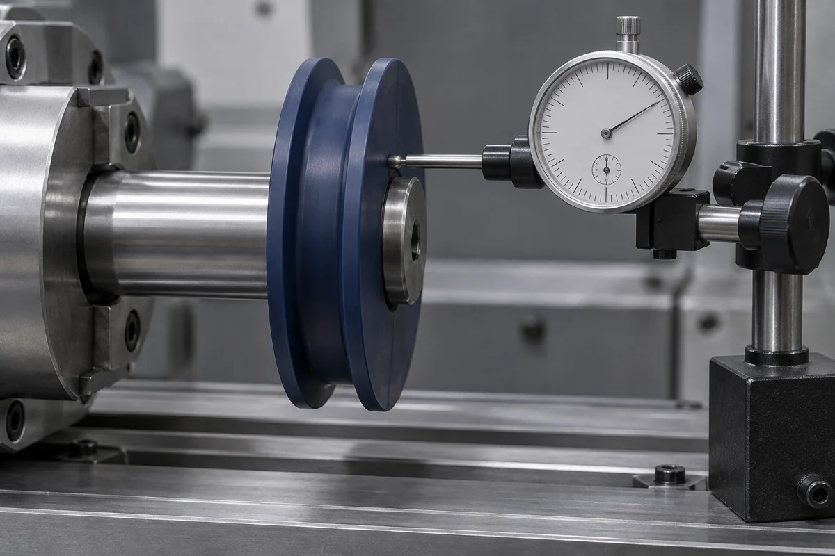
Record the cavity, material lot, trial stage and elapsed time after molding. Include conditioning where it matters to the selected compound. A dimensional change associated with moisture or temperature should not be mistaken for a fixture error or hidden by comparing samples in different states. Our material comparison explains this boundary.
Review the range across relevant cavities rather than relying on the best sample. If an insert is used, note its batch and loading method. A pattern associated with one cavity or insert condition can help guide the next investigation. Without sample identity, a pooled minimum and maximum may conceal the source of the variation.
Where a reading is outside the agreed limit, preserve the part and its setup information before making process changes. Check size, seating and local surface condition as separate observations. Changing several molding parameters at once can produce an acceptable sample without explaining which mechanism caused the original issue or whether it will recur.
Do not confuse runout with balance or service performance
A part can satisfy a runout check and still require a separate balance assessment for its application. Likewise, low indicator variation does not establish allowable speed, load or wear life. The Gates preventive-maintenance manual treats alignment and pulley condition as parts of a wider drive-system review; its system-specific recommendations are not universal tolerances for custom plastic wheels.
Agree the drawing requirement, inspection method, sample population and reporting terms before approving the trial. Add assembled functional checks where needed. A useful report states exactly what was measured and leaves unsupported conclusions out, making it possible for the supplier and customer to reproduce the decision when the next batch arrives.
Discuss a defined pulley application
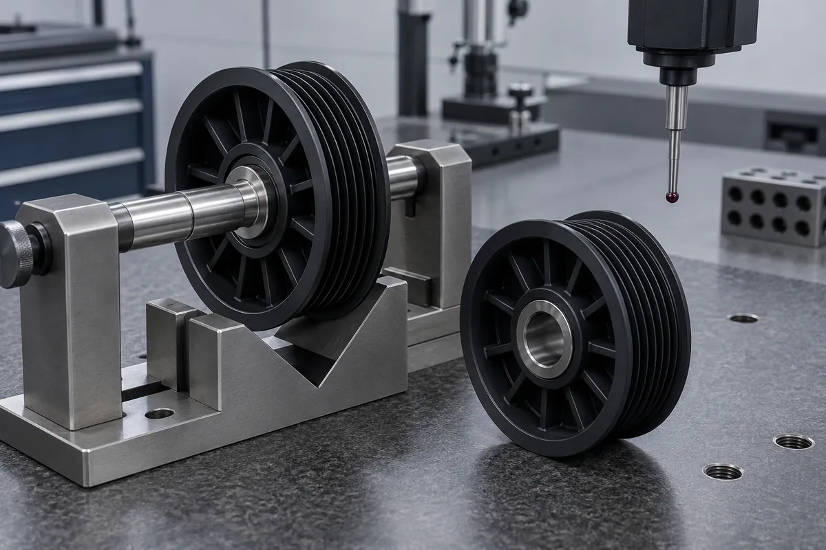
Explore our custom injection-molded plastic pulleys. Send the component drawing, mating belt or track, bearing specification and acceptance requirements to review tooling, molding and inspection as one supply scope.