
Medical Analyzer Housing: Cosmetics, Coating and Assembly
A non-implantable instrument cover needed acceptable appearance around the display, a controlled coated surface and a consistent fit with the lower housing.
This anonymized summary uses owner-confirmed project records. Its measurements describe the reported component checks, not a general molding capability or finished-device approval.
Process
Plastic Injection Molding
Component
PC/ABS Instrument Housing
Application
Non-implantable Equipment
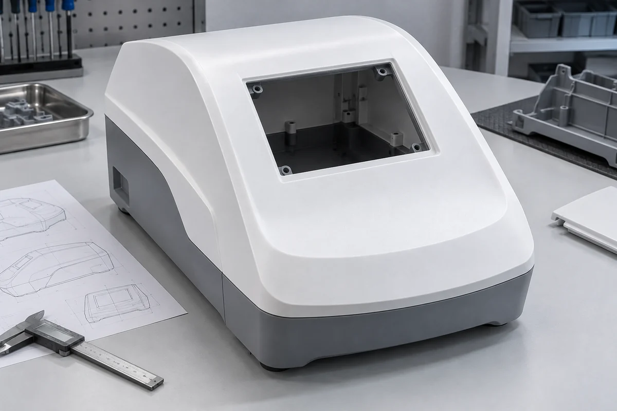
Project Overview
Define the cover as a component of the instrument
The upper housing carried the instrument's external cosmetic surface and display mounting interface. FECISION's recorded responsibilities included DFM, review of the tooling proposal, molding-process development, appearance criteria, color control and assembly-fit evaluation. A partner factory manufactured the mold. This case does not describe a complete instrument development or regulatory approval project.
Project scope
| Application | Upper cover and display support for a non-implantable tabletop analyzer |
|---|---|
| Material | PC/ABS; final purchase designation reported as SABIC CYCOLOY C6600-701 |
| Tool | Single-cavity tool with side gate and three slides |
| Released drawing | Revision C, June 10, 2026 |
| Production start | July 15, 2026 |
| Project roles | FECISION: DFM, tool coordination, process development and acceptance planning; partner factory: mold manufacture |
Manufacturing Challenge
Three issues needed separate evidence
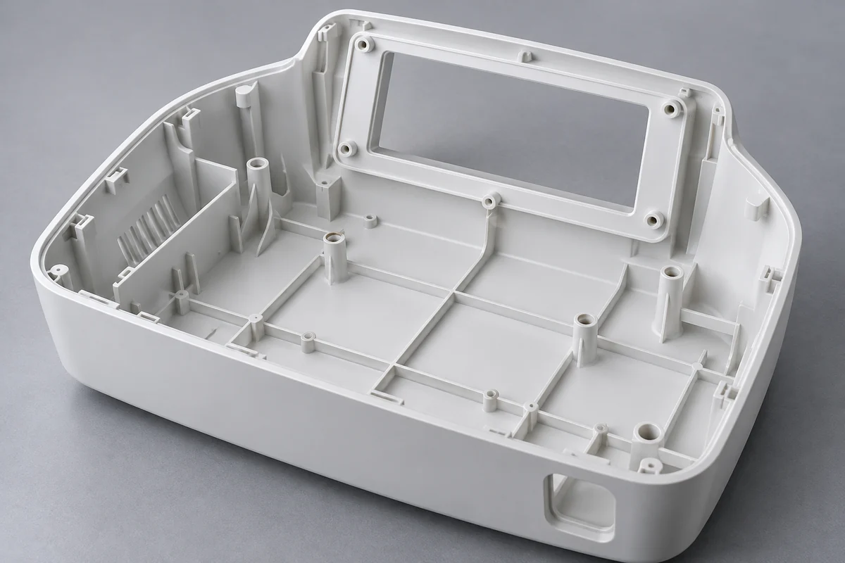
The T0 record identified a visible weld line around the display opening and sink on a broad cosmetic area. It also reported inconsistent performance of the internal conductive coating. The team needed to address appearance and coating preparation while preserving the display and lower-housing interfaces.
The initial notes associated the sink with a 3 mm wall region. They attributed the coating problem to surface contamination related to the trial material's release-agent history. That attribution guided the corrective work; the available summary is not a controlled study isolating every possible cause.
These issues could not be collapsed into a single acceptance number. Window flatness and assembled gap concerned geometry, visual inspection concerned the external surface, and coating measurements concerned a different functional layer. Each required a defined inspection method.
Engineering Response
Revise filling, wall distribution and surface preparation
The recorded tooling changes relocated the gate to move the weld line away from the designated cosmetic area. The team increased mold temperature for the subsequent trial and revised the broad wall region from 3.0 to 2.2 mm with a supporting rib network. These were project-specific changes, not a universal wall thickness or molding recipe.
For the coating route, the owner confirmed a change from the trial material designation CYCOLOY C6600-111 to the final purchasing designation CYCOLOY C6600-701, together with plasma treatment before coating. The resin designation is reproduced from the project confirmation; additive content and any material classification must follow the supplier's controlled documentation, not an inference from the suffix.
Because the material and preparation were changed together, this summary does not assign the result to either one alone. The revised configuration was assessed for appearance, dimensions, coating and assembly. The project record places trial-production acceptance on June 25, 2026, followed by the production start on July 15.
Recorded Results
Connect the reported values to their component checks
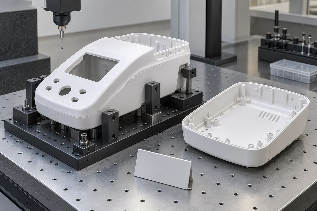
The supplied inspection summary reported the following ranges and checks. The window flatness and assembly-gap ranges lie within their respective stated limits. The appearance record also reported no visible weld line or sink on the designated cosmetic surface under the agreed inspection.
The color record does not specify its color-difference formula or full instrument configuration. Its ΔE values are therefore presented as the project's recorded comparison, not a transferable acceptance method for another housing. Likewise, the coating resistance is a component-level result, not evidence of whole-device electromagnetic compatibility.
| Characteristic | Recorded requirement | Reported result | Recorded method |
|---|---|---|---|
| Display-window flatness | ≤ 0.20 mm | 0.10–0.18 mm | CMM; nine points in the window region |
| Assembled housing gap | 0.30 ± 0.10 mm | 0.25–0.35 mm | Feeler gauge; eight locations per part |
| Color difference | ΔE ≤ 1.5 | ΔE 0.6–1.0 | D65 visual assessment and comparison with a reference panel |
| Coating sheet resistance | ≤ 0.5 Ω/□ | 0.2–0.4 Ω/□ | Four-probe method; five internal coating locations per part |
The intake lists a 100-piece trial-production batch and a cumulative 3,500 delivered housings through September 2026. Forecast monthly demand is not added to that delivered total. The supplied summary does not provide the population data needed to establish long-term process capability or to independently verify a production defect-rate claim.
Scope and Evidence
Preserve the limits of the completed review
The project record identifies extended disinfectant-wipe cycling and UV aging as unverified. The recorded application is indoor equipment; the case does not claim outdoor durability, sterilization suitability, biocompatibility, a flame classification or finished-device certification.
This anonymized summary uses project information supplied and confirmed by FECISION for public use. Original inspection reports and project photographs are not reproduced here. The supporting images are product design illustrations, not records of test results or customer-delivered parts.
The practical lesson is to keep cosmetic geometry, coating preparation and assembled fit in one coordinated review while retaining separate acceptance evidence. Passing one of those checks should not be used to close the others.
Related Engineering Guides
Prepare your own enclosure review
Bring the housing and its interfaces into the same quotation.
Send the controlled drawing, material, finish, counterpart revisions and approval requirements for your custom enclosure.
Request a Quote