
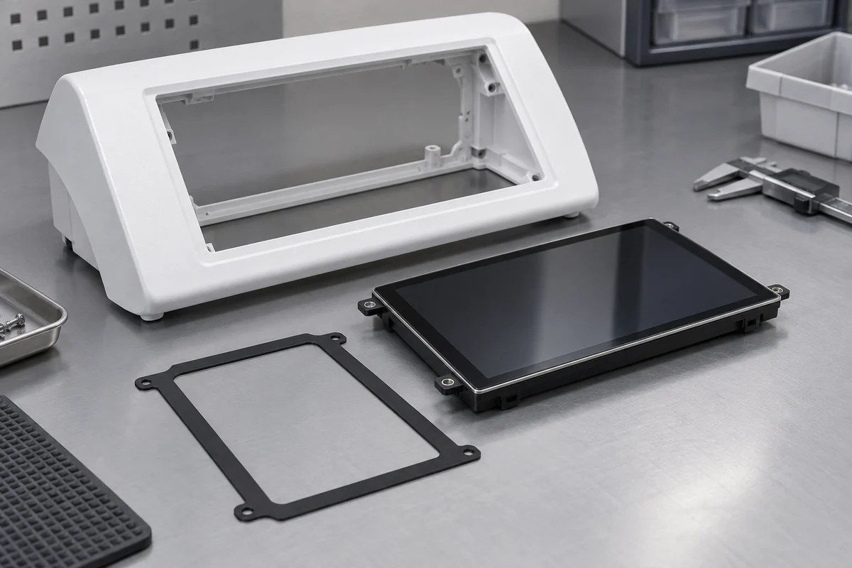
Product design illustrations. Final geometry, materials and acceptance criteria are project-specific.
A display opening can meet its drawing width and height while the installed screen still sits unevenly. The visible window, the supporting ledge and the mounting references perform different jobs. Combining them into one instruction such as hold the display area flat leaves both the mold designer and inspector guessing which relationship the assembly needs.
For a non-implantable instrument housing, begin by separating what the user sees from what locates the display module. The cosmetic reveal may be controlled by the bezel, while the module is fastened to an internal frame. A change to one interface can affect the other even if each loose component remains within its own nominal dimensions.
Give each display feature a defined function
The aperture provides clearance and the visible boundary. A seating ledge may support a gasket or window, while bosses or locating pins establish the module position. Identify these surfaces on the drawing and explain whether any are intentionally non-contacting. This prevents an inspector from measuring a convenient edge that does not actually locate the component.
Do not automatically assign the same tolerance to the visible opening and every hidden feature. A connector-access opening may tolerate more variation than the display alignment. Prioritizing the true functional chain gives the molding team room to resolve draft and wall transitions without consuming cost on unrelated dimensions.
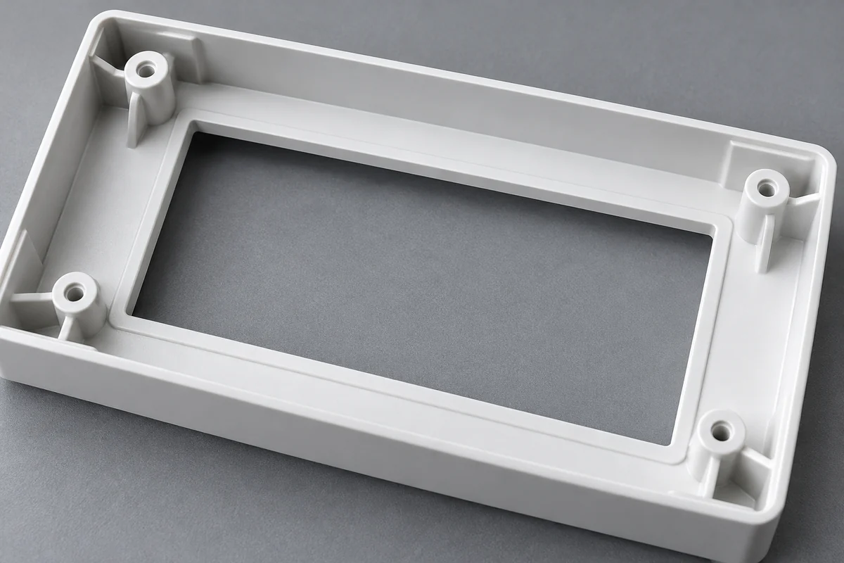
Build the stack from actual contacting surfaces
Follow the assembly from the housing datum through the ledge, gasket, display frame and fasteners. Identify which components determine the final location and which only provide clearance. Include counterpart revisions. A tolerance study based on an obsolete screen bracket can be mathematically correct but irrelevant to the parts that arrive for assembly.
Where a compressible gasket is present, avoid treating its free thickness as its installed height. The required compression and available movement belong to the gasket and assembly review. Do not solve a poor fit by increasing screw torque until the housing bends; that can hide the dimensional mismatch while changing stresses in the plastic and display support.
Document the free-state and assembled checks separately. A drawing may require a loose-part flatness measurement and an installed seam-gap check. Both can be useful, but they are not the same characteristic. The housing lid-gap guide provides the broader context for separating warpage from mating-part and fastening effects.
Preserve the cosmetic face during DFM changes
Bosses, rib junctions and sudden wall transitions behind a broad display surround deserve attention because their material distribution can affect the visible surface. Review coring and support geometry with the required load path rather than adding a thick pad wherever a screw is needed. A stronger-looking section is not automatically a better molded section.
Protolabs' screw-boss design discussion connects wall geometry and reinforcement to molding concerns. Treat such guidance as a starting point, not a universal dimension for every resin and screw. The actual fastener, material, geometry and intended service access need their own review.
Gate and flow decisions also matter around an aperture. A cosmetic improvement may relocate a weld line rather than remove every flow-related concern. Keep the proposed change tied to the drawing and sample evaluation, including the surfaces where a witness is acceptable. Avoid describing a simulation image as measured proof of the final molded result.
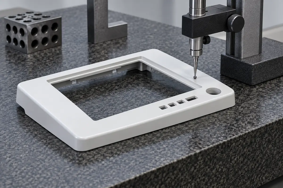
Make the inspection match the assembly question
Agree how the part is supported and which points are measured. An unsupported thin shell may behave differently from one seated in a fixture, so the inspection plan should specify the intended state. Clamping the part flat without an agreed rationale can conceal the free-state variation the drawing was intended to control.
Measure identified specimens and retain the location of the readings. A single maximum value can support a defined acceptance decision, but it does not explain the shape of a warped seating surface. Where the assembly issue needs more information, retain a feature map or measurement program rather than collecting additional readings without a clear purpose.
Approve the display relationship, not only the plastic
After dimensional checks, evaluate the controlled counterpart assembly. Confirm visible reveal, seating, mounting and the intended service procedure. Separate equipment-level checks from component inspection; a well-fitting bezel is not evidence of device safety or ingress protection.
Finally, capture the approved revisions and any remaining exclusions in the first-article release record. That makes a future display-module or gasket change visible as an interface change, instead of assuming that the previously accepted housing can accommodate every replacement.
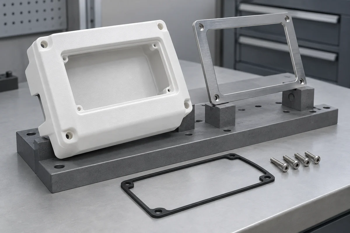
Discuss your custom enclosure
Explore our custom injection-molded medical device enclosures and the tabletop analyzer housing project. Share the controlled drawing, intended use, quantities and acceptance requirements. Component supply and finished-device qualification should have clearly assigned responsibilities.