
LSR Cable Grommet: Sealing and Pilot Validation
A soft LSR cable grommet needed consistent sealing-lip geometry without the internal bubbles and flange damage seen during early trials. The development work combined material-delivery review, tool venting, local geometry and demolding changes.
A subsequent 200-piece pilot underwent an assembled immersion check with no leakage reported under the recorded conditions. Customer validation remains ongoing; this is a pilot-stage case, not a completed mass-production launch.
Process
Four-cavity LSR molding
Pilot Check
200 assembled specimens
Your Interface
Custom Cable Grommets
Project Overview
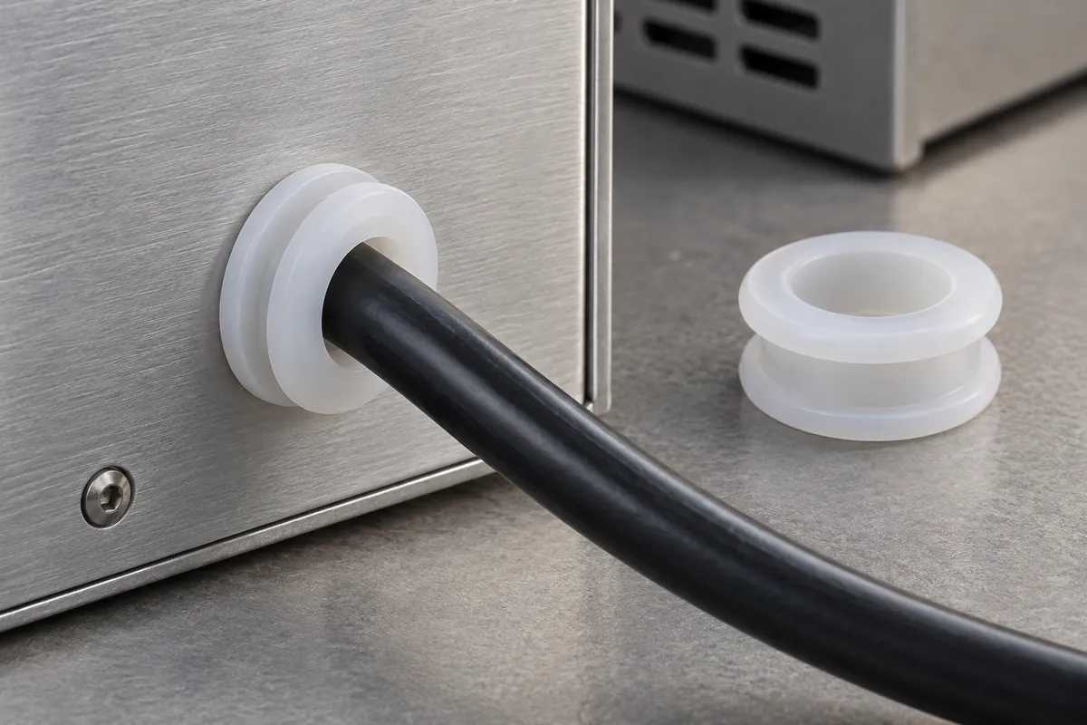
A soft interface between the cable and enclosure
The grommet was developed for a cable exit in an indoor medical-equipment enclosure. Its role was cable protection and a controlled sealing interface, not direct evidence of device approval or biological suitability. The project specified LSR with a Shore A 20 ± 2 hardness requirement.
FECISION handled DFM, mold-design review, molding development and component and assembly checks. An anonymous partner manufactured the four-cavity tool. Work began in April 2026, followed by tool trials and an August pilot. The customer has not yet completed system validation or released mass production.
Project scope
| Application | Cable exit in an indoor equipment enclosure |
|---|---|
| Material requirement | Liquid silicone rubber; specified hardness Shore A 20 ± 2 |
| Tool | Four-cavity LSR tool with cold-runner feed and vacuum venting |
| Project roles | FECISION: DFM, mold-design review, molding development and component/assembly checks; partner: mold manufacture |
| T2 stage | July 25, 2026 · 80 parts for appearance, dimensions and lip-interference review |
| Pilot stage | August 10, 2026 · 200 parts; assembled immersion check on all 200 |
| Current status | Customer validation ongoing; not released to mass production |
Manufacturing Challenge
Address internal bubbles and damage at a delicate lip
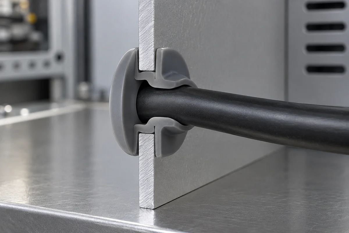
The initial 30-part T0 trial on June 15 recorded internal bubbles, inconsistent sealing-lip interference and tearing during demolding. The early lip-interference range was reported as 0.15–0.45 mm, compared with the later controlled requirement of 0.30 ± 0.05 mm.
These observations required different checks. Bubbles prompted investigation of mixing and air escape. Variation at the lip required a geometry and inspection review. Tearing also required attention to local draft and the way the part was removed from the tool. No single defect-rate reduction is calculated from the available trial summaries.
Engineering Response
Coordinate material delivery, venting and lip release
The development record describes added vacuum venting and a mixing/de-airing review, followed by a revised local lip geometry and a change in draft and ejection position. These are reported as combined development actions, not a controlled experiment proving that one setting caused every improvement.
T1 comprised 50 parts on July 5. The drawing advanced to Revision B on July 20, followed by an 80-part T2 trial on July 25. The owner clarified that T2 covered appearance, dimensions and lip-interference inspection only. It did not include the later assembled immersion test.
The revised lip-interference range was reported as 0.28–0.33 mm. The dimensional record describes section/optical inspection and a pilot sampling quantity of 10 parts. This geometric check is kept separate from the 200 assembled specimens used for immersion.
Recorded Results
Test the assembled interface, not a loose silicone part
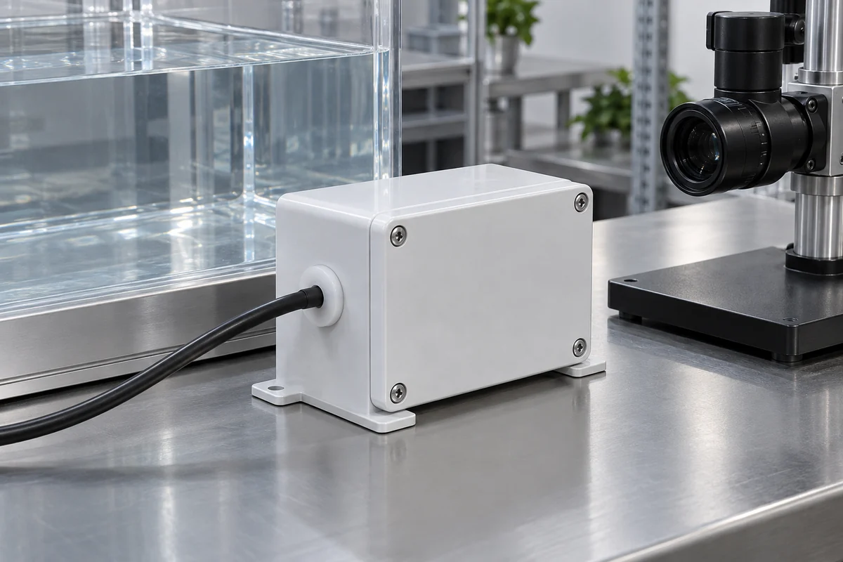
The August 10 pilot produced 200 parts. The owner confirmed that all 200 were tested in an assembled condition: the grommet was seated in a 20 mm metal-panel opening with a 5 mm cable. The fixture's remaining openings and cable ends were sealed before immersion.
The reported IPX7 immersion check used 1 m water depth for 30 minutes, with no leakage observed in those 200 assemblies. This is an owner-confirmed project result under the stated configuration. It is not presented as independent certification or a rating for other panel and cable combinations.
| Check | Recorded condition | Reported result | Population and scope |
|---|---|---|---|
| Sealing-lip interference | 0.30 ± 0.05 mm | Reported range 0.28–0.33 mm | Section/optical method; pilot sampling record specifies 10 of 200 parts |
| Assembled immersion | 1 m water depth, 30 minutes | No leakage observed in 200 assemblies | August pilot; 20 mm panel opening and 5 mm cable; unrelated fixture openings sealed |
| Cleaning screen | 99% IPA, 100 back-and-forth wipe cycles | No cracks; reported hardness change no more than 2 Shore A | Three specimens; limited component screen, not cleaning or disinfection validation |
No separate IP6X dust test was performed. Dust protection remains untested, so this case does not claim full IP67 certification. The 200-piece no-leak observation also does not establish long-term sealing life or a zero-failure rate for future production.
The three-specimen cleaning screen used 99% IPA and 100 back-and-forth cotton-cloth wipe cycles. The reported observations were no cracking and a hardness change no greater than 2 Shore A. These limited results do not validate disinfectant effectiveness, all cleaning agents, sterilization or biological contact.
Validation Boundary
Keep pilot progress separate from production approval
Customer validation remains in progress. Long-duration compression behavior, sterilization exposure and biological-contact suitability are not established by the reported checks. No mass-production delivery quantity, certified medical-grade claim or universal service-life result is asserted here.
The public case uses project records supplied and confirmed by FECISION for anonymous publication. Original laboratory reports and project photographs are not reproduced here. The product design illustrations explain the interface and inspection concepts; they are not evidence of the recorded measurements.
For another application, the useful starting point is the same separation of responsibilities: control the molded geometry, define the panel and cable, then agree the assembly tests and remaining system qualification. A change to any of those inputs needs review before transferring the result.
Related Engineering Guides
Plan your cable-entry component
Review the grommet with its panel and cable.
Send the controlled drawings, material requirements and proposed assembly validation scope.
Request a Quote