
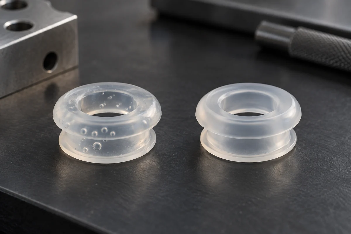
Product design illustrations. Final geometry, materials and acceptance criteria are project-specific.
A bubble inside a silicone grommet, a thin flash film and a torn lip are different defects even when they appear in the same trial. Treating them all as a need for more pressure or a longer cure can create new problems. A useful investigation first describes where the defect occurs, when it appears and which cavities or material conditions are associated with it.
Separate visible appearance from functional acceptance. A mark outside the contact area may have a different consequence from a discontinuity crossing a sealing lip. Agree the relevant limits before sorting samples. That does not mean ignoring appearance; it means documenting which defect characteristics affect assembly, customer appearance requirements or a controlled sealing function.
Locate bubbles before assigning a cause
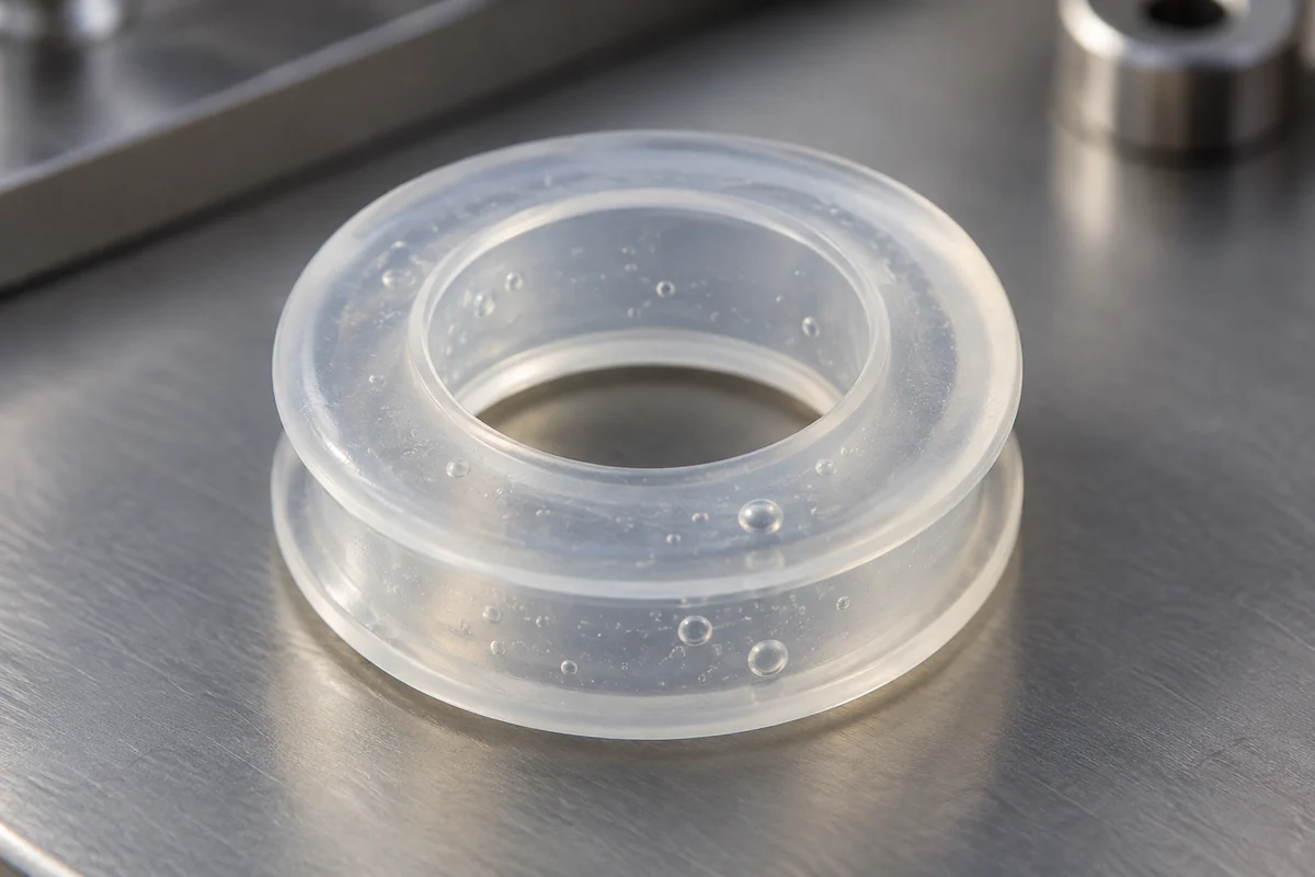
Record whether the feature is internal or open to the surface, whether it repeats in one location and whether it occurs in all cavities. Transmitted light or a prepared section can help distinguish a true void from a surface reflection in a translucent part. Keep specimen identity during this work so the inspection remains connected to the molding condition.
Air can enter during material handling or become trapped during cavity filling. Check the delivery and mixing system as well as the tool. Review changes around material replenishment, startup and interrupted cycles. A repeated defect near an end-of-fill region suggests a different investigation from random bubbles distributed throughout parts from every cavity.
Review filling and air escape as one process
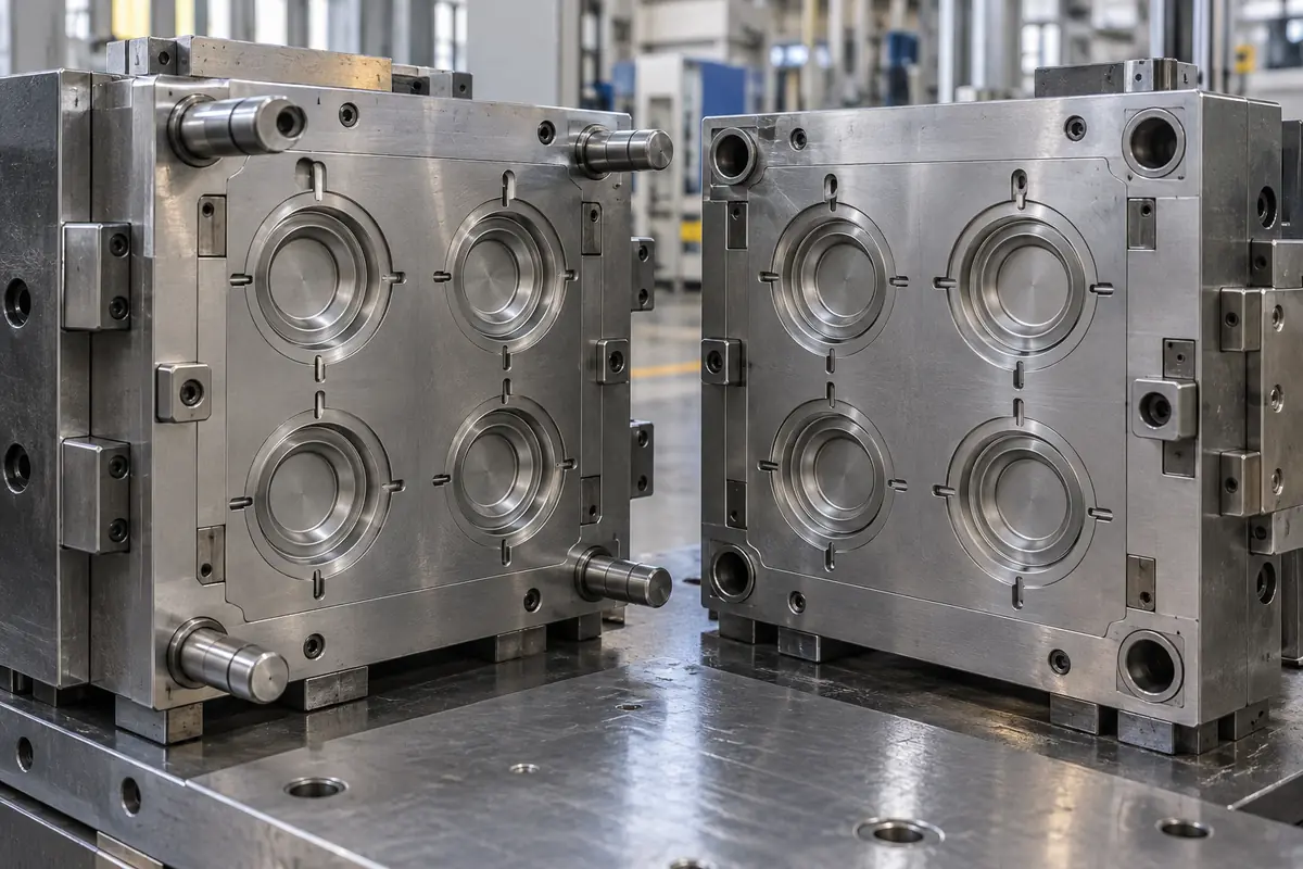
Discuss gate position, flow progression and vent access with the toolmaker. A thin lip or an enclosed region can be difficult to fill without trapping air. The WACKER silicone-rubber processing guide provides manufacturer background on tooling and processing. Use the relevant grade and tool guidance rather than applying one generic vent or temperature value to every LSR part.
Vacuum can be part of an appropriate tool strategy, but the presence of a vacuum connection does not prove that the cavity is evacuated effectively. Check sealing, timing, maintenance and the actual process sequence. Record the investigation and assess the resulting parts. A setting shown on a machine screen is not the same as evidence of the condition at every cavity.
Keep changes controlled. If the material delivery, vent geometry and fill settings all change at once, the new configuration may work without revealing which change mattered. That can be acceptable for a documented development iteration, but it should not become an unsupported statement that one adjustment universally eliminates bubbles.
Distinguish flash from a gate or parting witness
Describe flash by its location and acceptable extent rather than simply asking for a flash-free part. Tool mating surfaces, closure, wear and the molding process deserve review. A thin film across a cable-contact surface may require a different response from a removable vestige in a non-functional region. Inspect before and after any agreed trimming operation.
Do not automatically solve flash by reducing fill until incomplete lips appear. Review the process window together with tool condition and cavity balance. On a multi-cavity tool, one cavity may flash while another is difficult to fill. Cavity-specific inspection is more useful than averaging all samples into a single acceptance number.
Find out when a lip tears
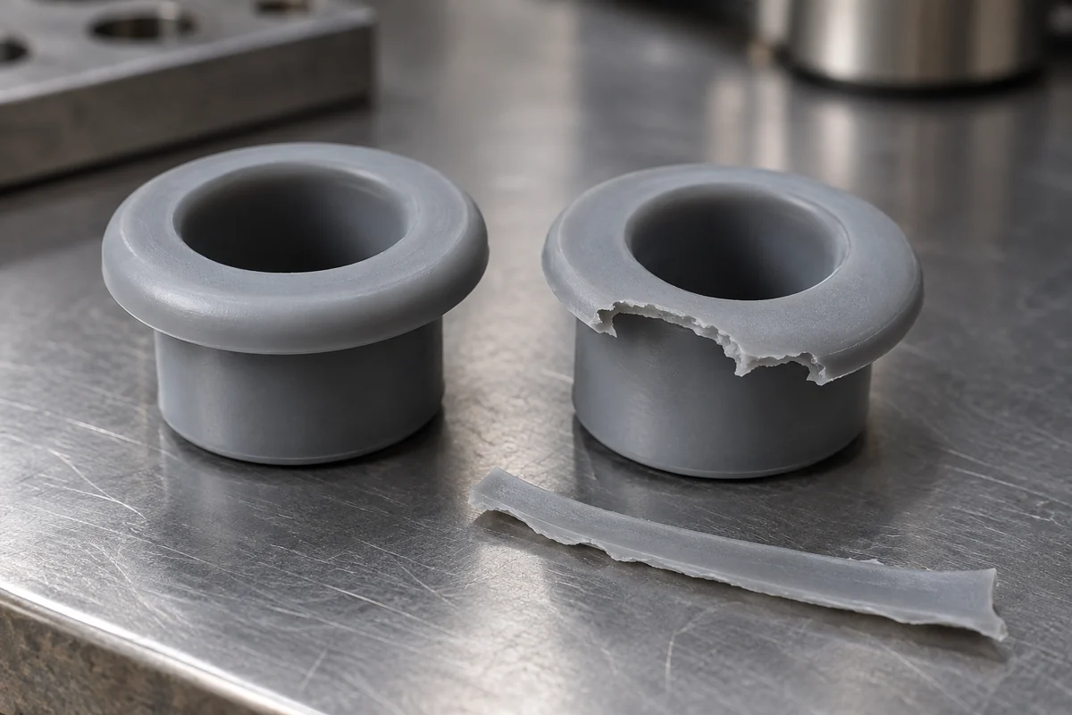
A torn flange may originate during demolding, trimming, packaging or installation. Inspect parts at the earliest practical stage and observe the sequence safely through normal machine procedures. If the tear is already present before trimming, changing packaging will not address it. If it appears only after insertion, examine the panel edge and assembly method as well as the molded geometry.
Review local thickness, sharp transitions, undercuts and the way the part is released. Tool surface condition, draft and removal direction can concentrate strain at a delicate lip. The compound and cure condition also need appropriate review. Do not claim a material is unsuitable merely because one uncontrolled extraction method damaged an otherwise acceptable trial part.
Where a geometry or ejection change is made, verify that it preserves the sealing contact and installation function. A larger radius or altered lip may reduce local damage but also change fit. The corrected drawing, inspection plan and assembly test configuration should stay synchronized throughout the trial sequence.
Release a stable process with a traceable acceptance plan
Keep representative accepted and rejected samples, with photographs and controlled descriptions where permitted. State inspection lighting, magnification and the surfaces to assess. “No visible bubbles” under a specified inspection method is a narrower, more useful statement than an unqualified promise that the material contains no internal discontinuities of any size.
Finally, separate trial acceptance from production controls. A successful sample batch supports the tested configuration but does not establish future zero-defect performance. Agree routine inspection, cavity identification, startup checks and the response to a change in material or tooling. This turns defect correction into a repeatable manufacturing definition rather than a temporary machine adjustment.
Review a defined cable-entry assembly
Explore our custom LSR silicone cable grommets and the cable-grommet pilot validation case study. Send the part drawing, panel and cable specifications, service conditions and acceptance plan to scope tooling, molding and inspection together.