
Precision connector components · Made to your design
Custom Board-to-Board Connector Housings
Define the molded housing around the board spacing, mating motion and interfaces it must control.
FECISION reviews custom molded plastic housings for customer-designed board-to-board and mezzanine connector assemblies. Bring the housing drawing together with the counterpart, contact interface and board support arrangement. We assess the molded features, material requirements, tooling approach and inspection scope against that assembly definition, then prepare a project-specific manufacturing quotation.
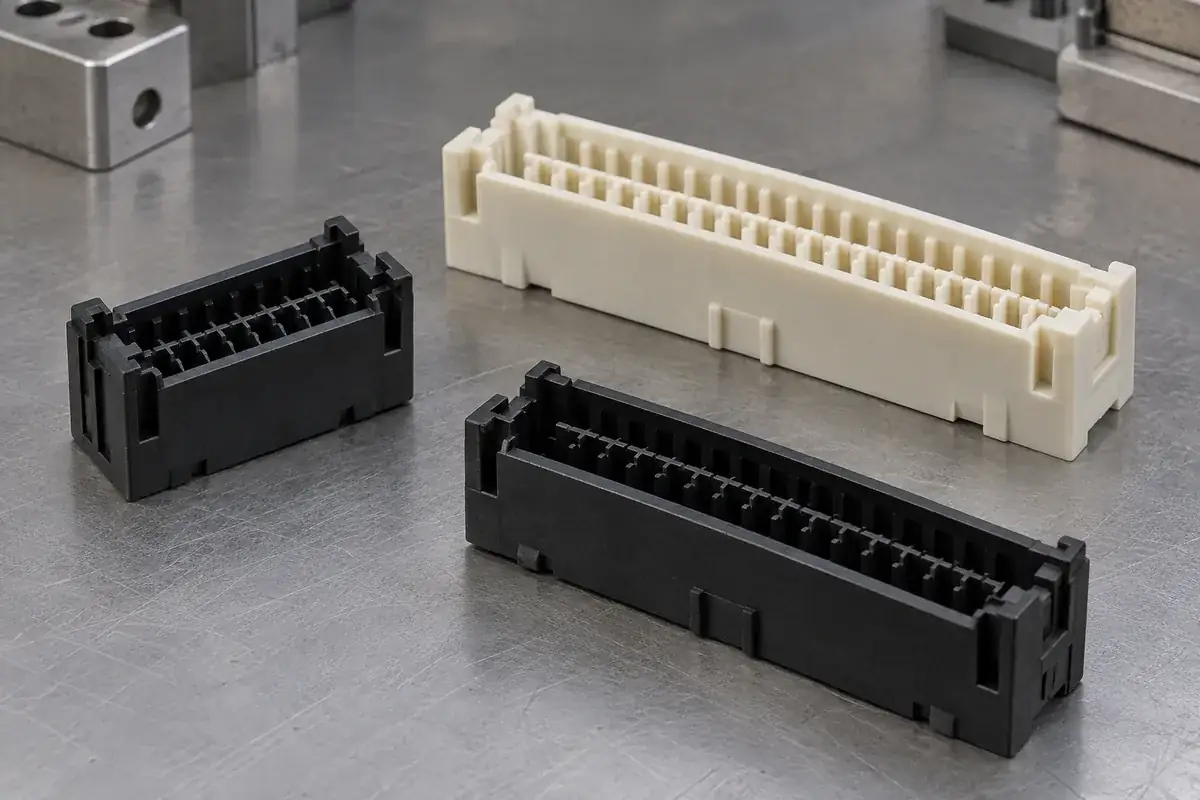
Product details
The molded interfaces that guide a board-to-board assembly
Product design illustrations show empty housing concepts and their mechanical features. The geometry, material and acceptance requirements are defined for your drawing and counterpart.
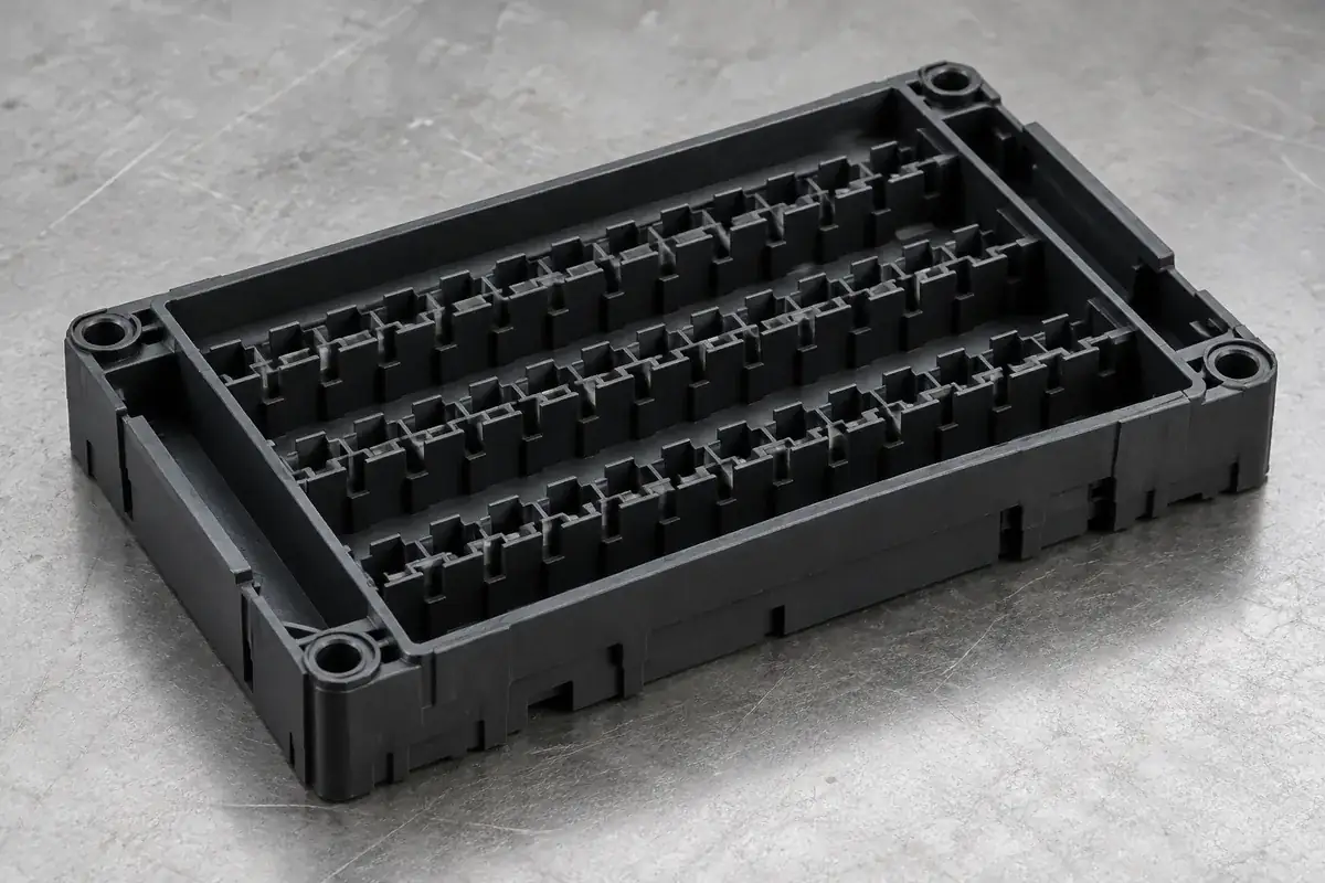
Contact-cavity envelope
Product design illustration: define contact entry, local retention features and the cavity relationship to the mounting references.
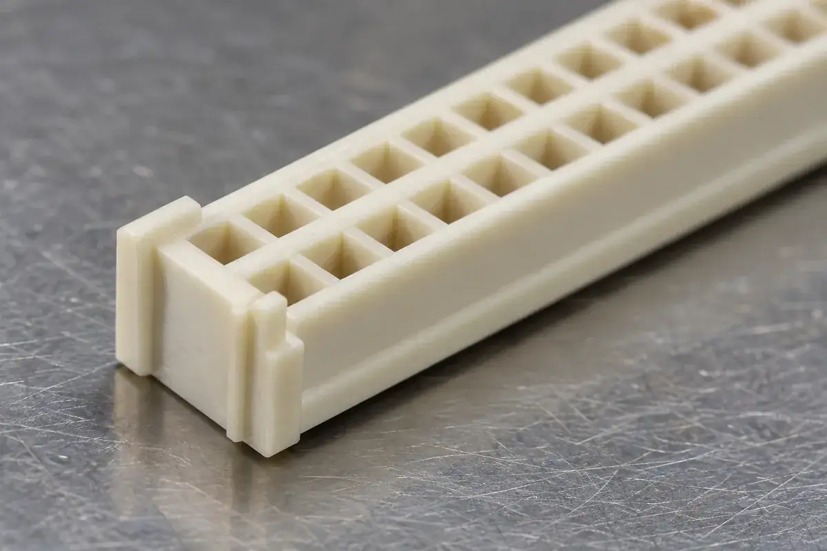
Polarization and guide features
Product design illustration: arrange the key and guide surfaces so correct alignment occurs before sensitive interfaces engage.
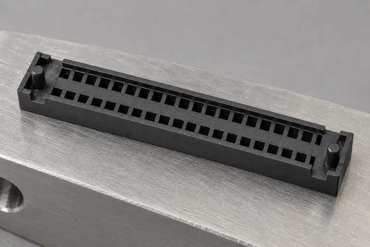
Board locating and seating
Product design illustration: assign separate roles to locating pegs, seating surfaces and any retention features.
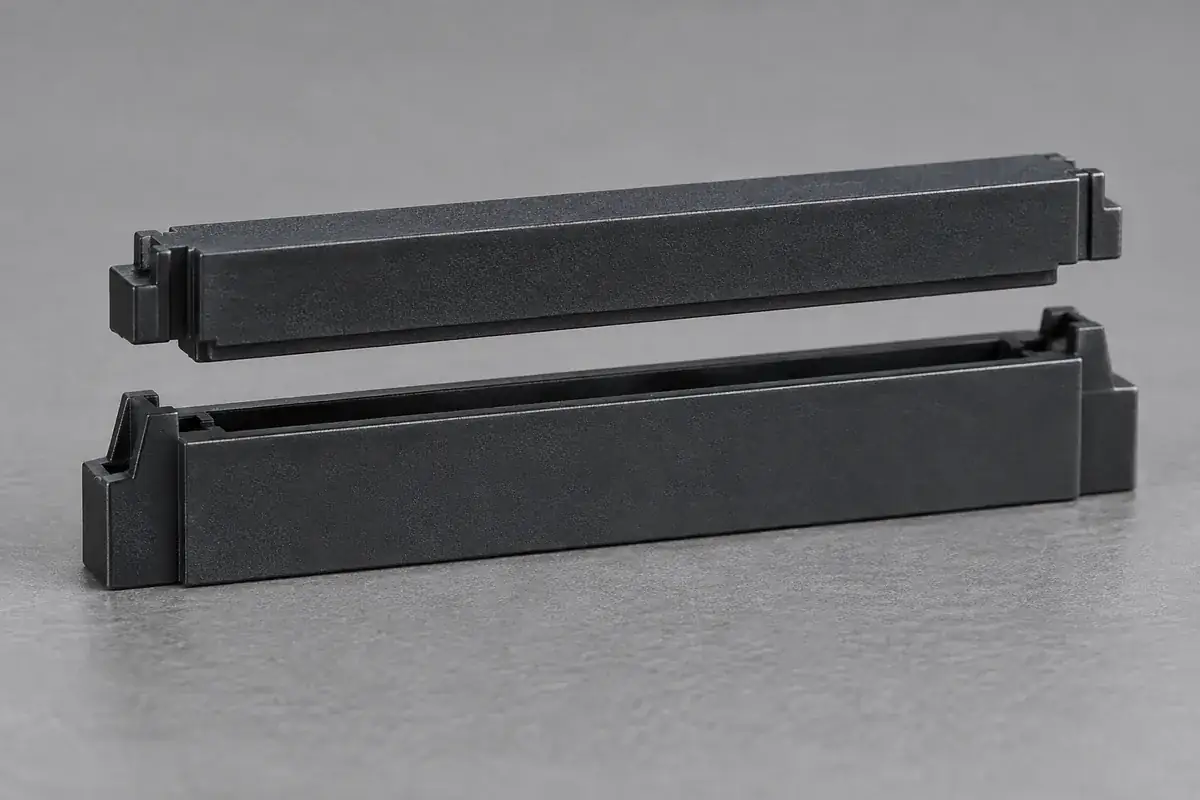
Mating housing relationship
Product design illustration: review the approach, guide engagement, final position and available clearance as a complete pair.
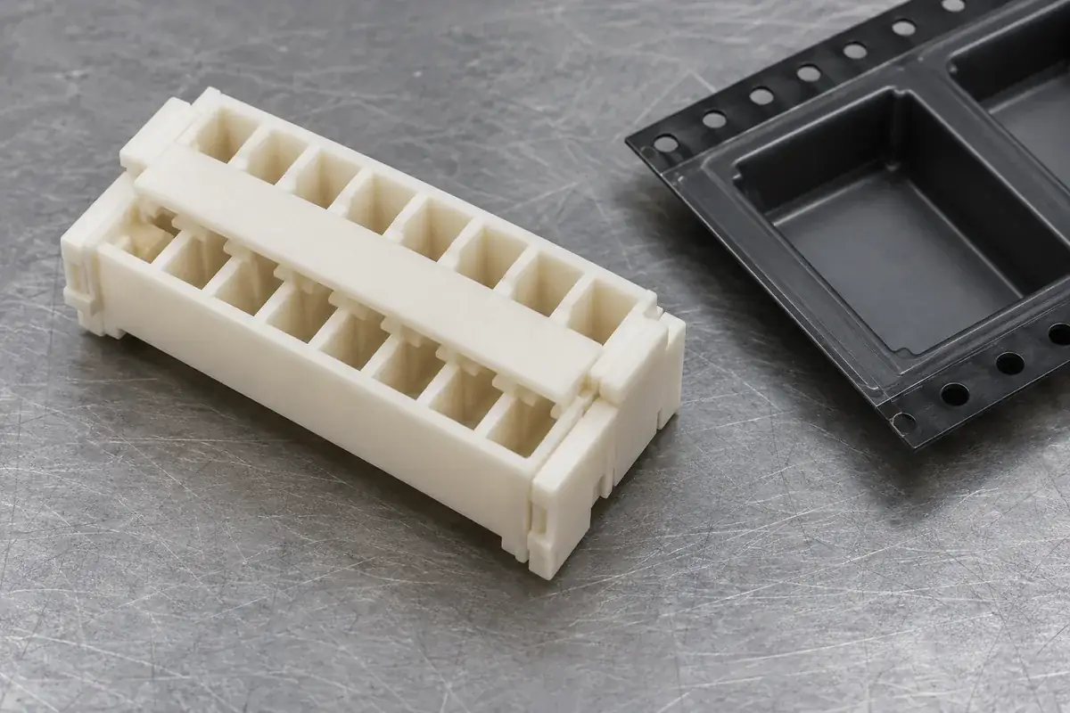
Assembly handling surface
Product design illustration: coordinate pickup access, the molded contact surface and the packing orientation with the intended assembly process.
Illustrative configurations. Final specifications follow your approved drawings.
Application fit
Molded components for defined board-to-board interfaces
The supplied component is the customer-defined plastic housing. Its role may include positioning contacts, guiding the mating pair, establishing a seating relationship or supporting assembly handling. Review each function against the actual board and counterpart arrangement.
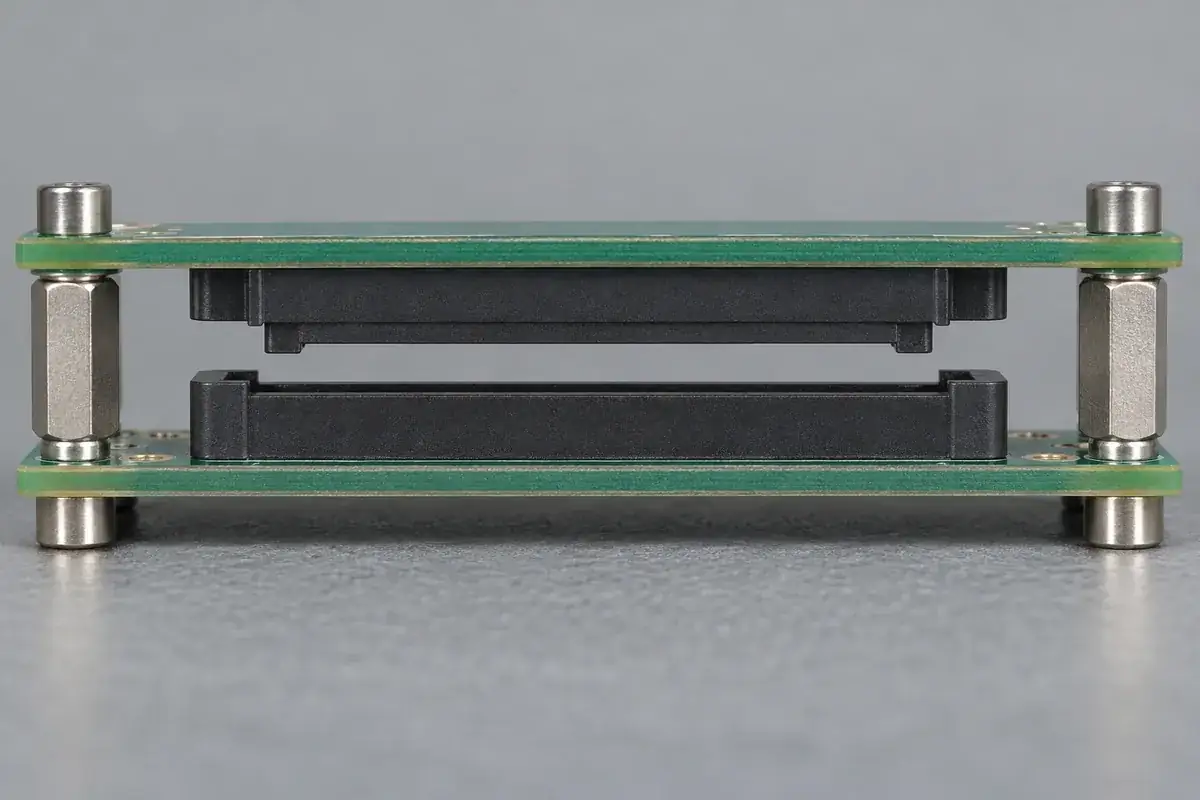
Mezzanine connector housings
Empty molded bodies for connectors joining parallel boards. Review the housing heights, guide relationships and mounting references with the standoffs or other hardware that establishes the final board separation.
Keyed mating shells and guide bodies
Customer-defined polarization ribs, receiving slots and guide walls. Correct and incorrect approach sequences should be considered together so the intended pair enters while defined incompatible orientations encounter a suitable stop.
Contact carriers with board-mounting features
Housings that combine contact cavities with locating pegs, seating feet or handling surfaces. The cavity, contact and installation method remain a controlled interface even when contacts are assembled by another supplier.
Quote-ready inputs
What to send for a meaningful quotation
Use the same drawing and requirements for every proposal. Mark open decisions explicitly so that a low price does not conceal a different deliverable.
| Area | Please provide | Review before release |
|---|---|---|
| Housing and counterpart | Controlled CAD, drawing revisions, mating housing and contact-interface definition. | Identify guide surfaces, contact travel, retention details and features that must remain unchanged. |
| Board stack and supports | Board references, intended separation, mounting holes, standoffs and nearby interfaces. | Connect housing height and location to the system that establishes the assembled board position. |
| Mating and handling sequence | Approach direction, available alignment movement, assembly method and pickup or packing requirements. | Review first contact, guide engagement, seating, permitted overtravel and access for the intended process. |
| Material and exposure | Specified resin grade, color, reinforcement, documentation and relevant manufacturing or service exposure. | Evaluate the exact grade and part configuration against the required conditions and approval evidence. |
| Inspection and acceptance | Functional datums, critical features, sample state, cavity traceability and any agreed mating checks. | Separate molded geometry verification from populated-assembly performance and define the evidence for each. |
| Production and delivery | Trial quantities, initial and repeat demand, packing orientation and schedule. | Agree tooling development, sample approval, production release and component protection during transport. |
From drawing to approval
Connect the molded definition to the assembled interface
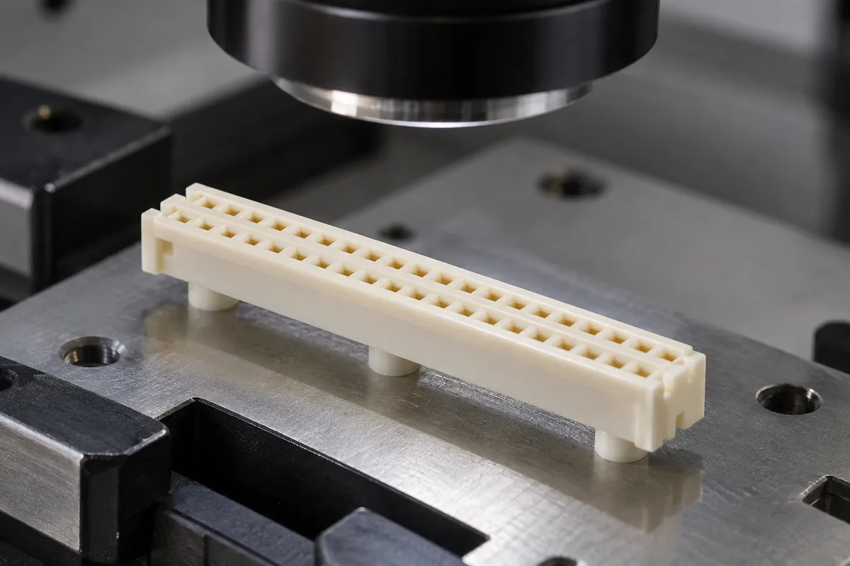
Establish the mechanical reference chain
Review the housing, mating component and board arrangement together. Identify the seating plane, lateral references, intended engagement and the features that control movement during assembly. Resolve conflicting reference schemes before assigning final plastic tolerances.
Review material and moldable geometry
Evaluate cavity details, thin walls, keys, pegs and pickup surfaces for the selected grade and tooling approach. Discuss gate, parting-line and ejection locations in relation to functional surfaces. Proposed geometry changes are reviewed against the mating sequence before approval.
Evaluate identified molded samples
Inspect samples by cavity and revision using the agreed support and conditioning state. Compare local dimensions with combined fit checks where included. If an assembly issue appears, retain the counterpart and fixture definition so the result can be traced to a meaningful configuration.
Release the agreed component configuration
Record the approved drawing, resin, tooling configuration, packing and inspection requirements. Keep any separate contact or complete-assembly evaluation connected to the same revision. Subsequent changes to a key, guide, peg or seating surface receive a review of the interface they affect.
Practical engineering and buying guides
Decisions to make before production
- Board-to-Board Housing Stack Height: Where the Gap GoesTrace board spacing through housing seats, engagement depth and mechanical supports to define a stack height that works in the assembled product.
- Mezzanine Housing Alignment with Multiple ConnectorsUnderstand how guide geometry, board location and multiple connector pairs interact, then choose where alignment freedom belongs in a mezzanine assembly.
- Polarization Keys for Board-to-Board Connector HousingsPlace polarization keys where they reject an incorrect orientation before sensitive features engage, while preserving guide strength and assembly access.
- Mating Lead-In Chamfers in Connector HousingsDesign connector housing lead-ins around capture, available movement and final guide engagement, balancing easier entry with wall strength and location.
- Contact-Cavity Retention in Board-to-Board HousingsSeparate contact guidance, insertion travel and retention in molded board-to-board cavities, with clear load paths and assembly-specific acceptance.
- Mounting-Peg Fit for Board-to-Board HousingsChoose locating-peg fits from the board assembly sequence, separating placement guidance, seating and retention while avoiding conflicting references.
- Controlling Board-to-Board Connector Assembly OvertravelTrace what stops a board-to-board assembly after engagement, and coordinate housing shoulders, supports and press travel to avoid unintended compression.
- Pick-and-Place Surfaces on Connector HousingsPlan molded pickup pads and removable caps around nozzle access, stable handling and cavity clearance, then connect the design to packing and placement.
- Mezzanine Housing Warpage and Functional FitRelate housing bow and twist to board seating, guide engagement and contact position, using defined free-state and assembled measurement conditions.
- A Cavity Inspection Plan for Board-to-Board HousingsBuild a housing inspection plan that links mold-cavity identity to seating, guides and contact interfaces, with defined fixtures and meaningful fit evidence.
Related connector manufacturing scopes
Explore empty insulating bodies, components molded around metal terminals and the precision mold inserts used to form them. Each scope has its own drawings and acceptance requirements.
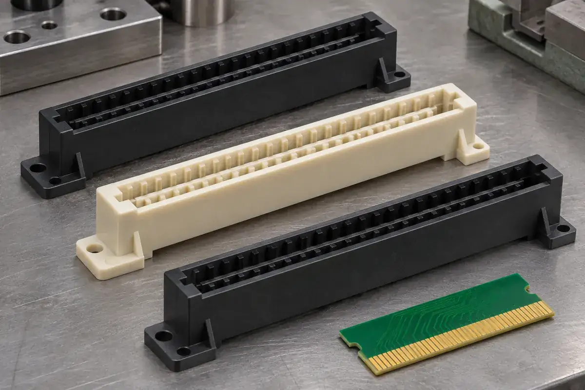
Custom Card-Edge Connector Housings
Custom molded card-edge connector housings. Review PCB thickness, slot entry, contact cavities, polarizing features and mounting references for your design.
Review the application →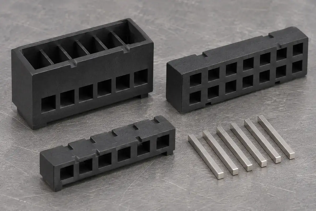
Custom Pin Header and Socket Insulator Bases
Custom molded pin header bases and socket insulators made to drawing. Review pin support, contact cavities, body position, standoffs and assembly requirements.
Review the application →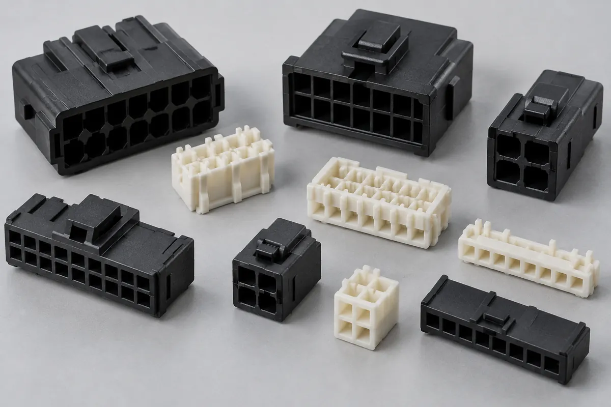
Connector Insulators & Terminal Carriers
Custom molded insulating bodies and terminal carriers. Define terminal interfaces, locating references, exact resin and component acceptance.
Review the application →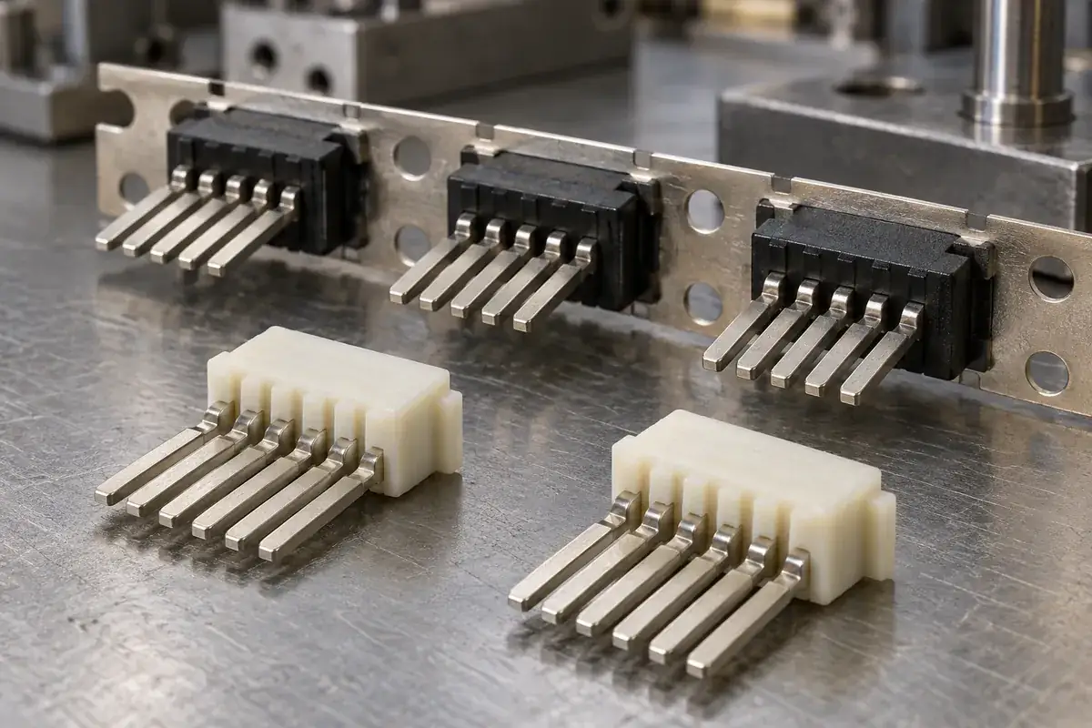
Custom Insert-Molded Connector Components
Custom connector components combining stamped terminals and molded plastic. Review contact location, carrier strips, resin shutoffs, tooling and inspection with FECISION.
Review the application →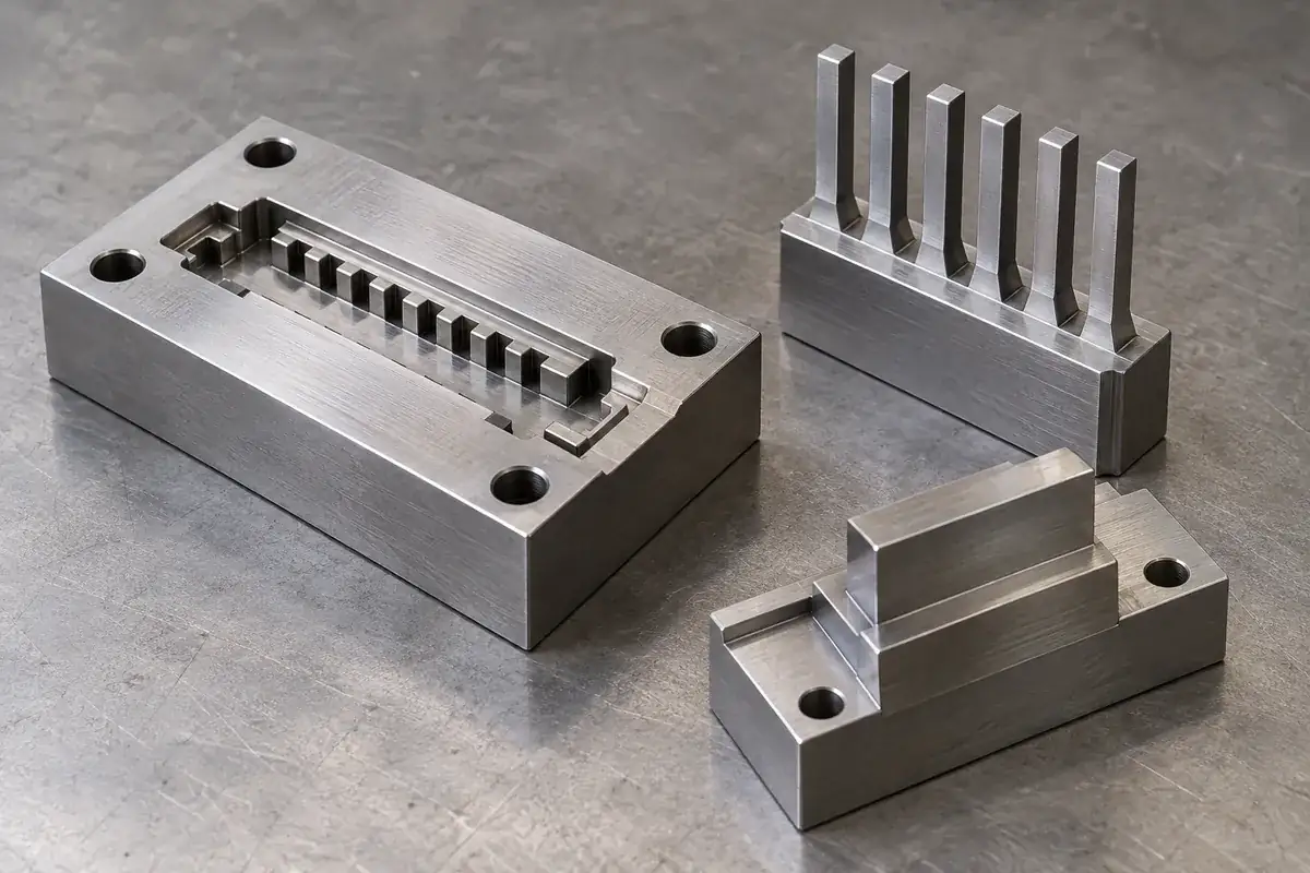
Precision Connector Mold Inserts
Custom steel mold inserts for connector tooling: cavity inserts, thin cores and comb features. Review drawings, locating fits, finishing and replacement scope with FECISION.
Review the application →Before you request a quote
Are these complete electrical connectors?
This page covers custom molded plastic housing components. Contacts, plating, assembly and electrical qualification require their own agreed scope. A housing quotation does not assign an electrical rating or certify a completed connector.
Can you quote a housing from its outside dimensions?
Outside dimensions are useful for an initial discussion, but a manufacturing quotation needs the controlled geometry and functional interfaces. Include the mating part, contact cavities, board references, material requirements and expected quantities.
How should stack height be specified?
Define the board reference surfaces, housing seating conditions and intended mated position. Include the supports that set board separation. The housing overall height alone does not define contact engagement or the permissible assembly travel.
Can a custom housing be described as floating?
A floating connector requires an intentional movement mechanism and defined limits. Clearance in a molded shell does not establish that behavior by itself. Share the complete mechanism and its requirements so the plastic contribution can be reviewed.
Can molded pegs retain the housing on the board?
A peg may guide, locate or retain depending on its design. Provide the finished board-hole definition, support method and installation sequence. A compliant retaining feature needs different evaluation from a simple locating peg.
What dimensional inspection can be included?
Agree the feature list, datums, sample condition, cavity identification and reporting needs at quotation. Optical measurement, other suitable methods and defined functional checks can be considered for the actual geometry; complete-assembly acceptance remains separately identified.
Your next step
Discuss the part with its intended function.
Send the housing and counterpart drawings with the board stack and assembly sequence. We will review the molded interfaces and prepare a component manufacturing scope with clear sample and inspection requirements.
Explore our connector injection molding service or review other connector components and mold inserts.