
Precision connector components · Made to your design
Custom D-Sub Connector Insulators
Locate the contacts and shell from a shared set of assembly references.
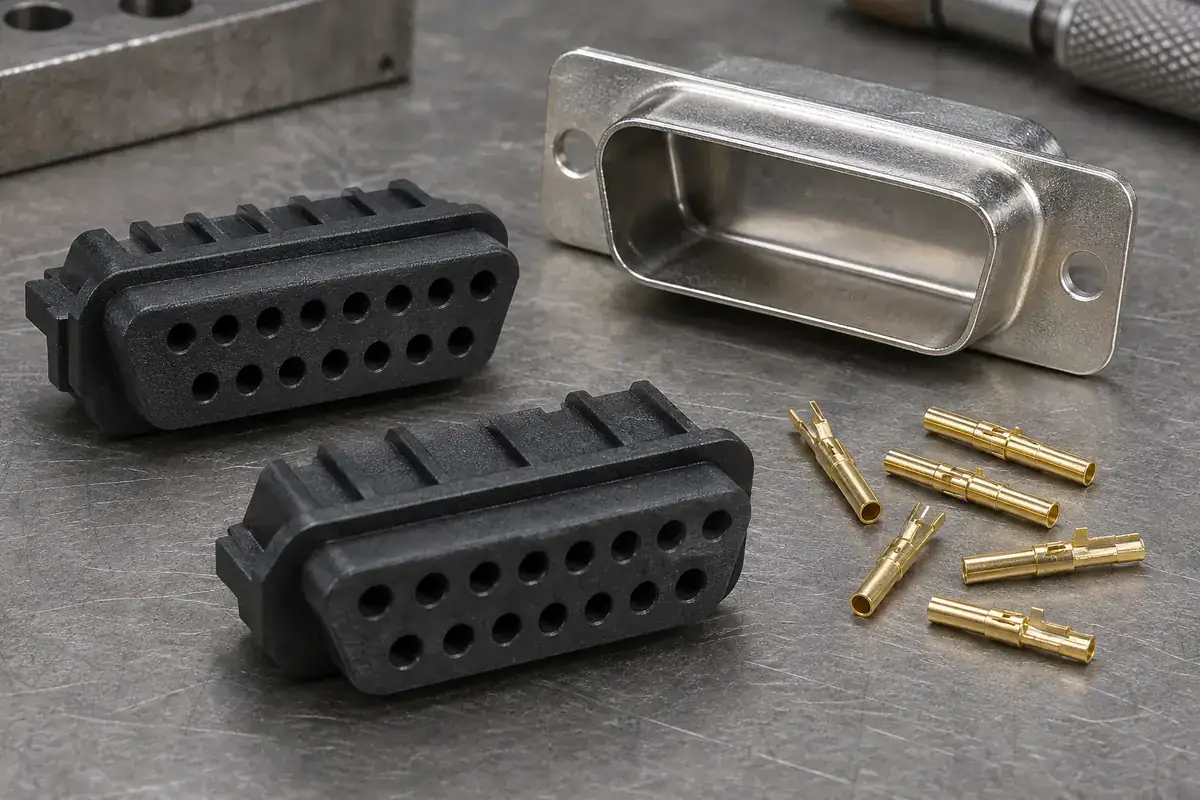
FECISION coordinates injection molding for drawing-defined D-sub insulating inserts and related contact-locating components. Share the plastic drawing with the contact and metal-shell definitions. We review the cavity pattern, seating faces, shell interface and assembly sequence to establish the molded-part scope and the evidence needed for sample approval.
Product details
Explore the contact pattern, locating faces and shell interface
Product design illustrations show how molded insulating components relate to contacts and a D-shaped shell. The controlled drawings define the actual contact arrangement and mating interface.
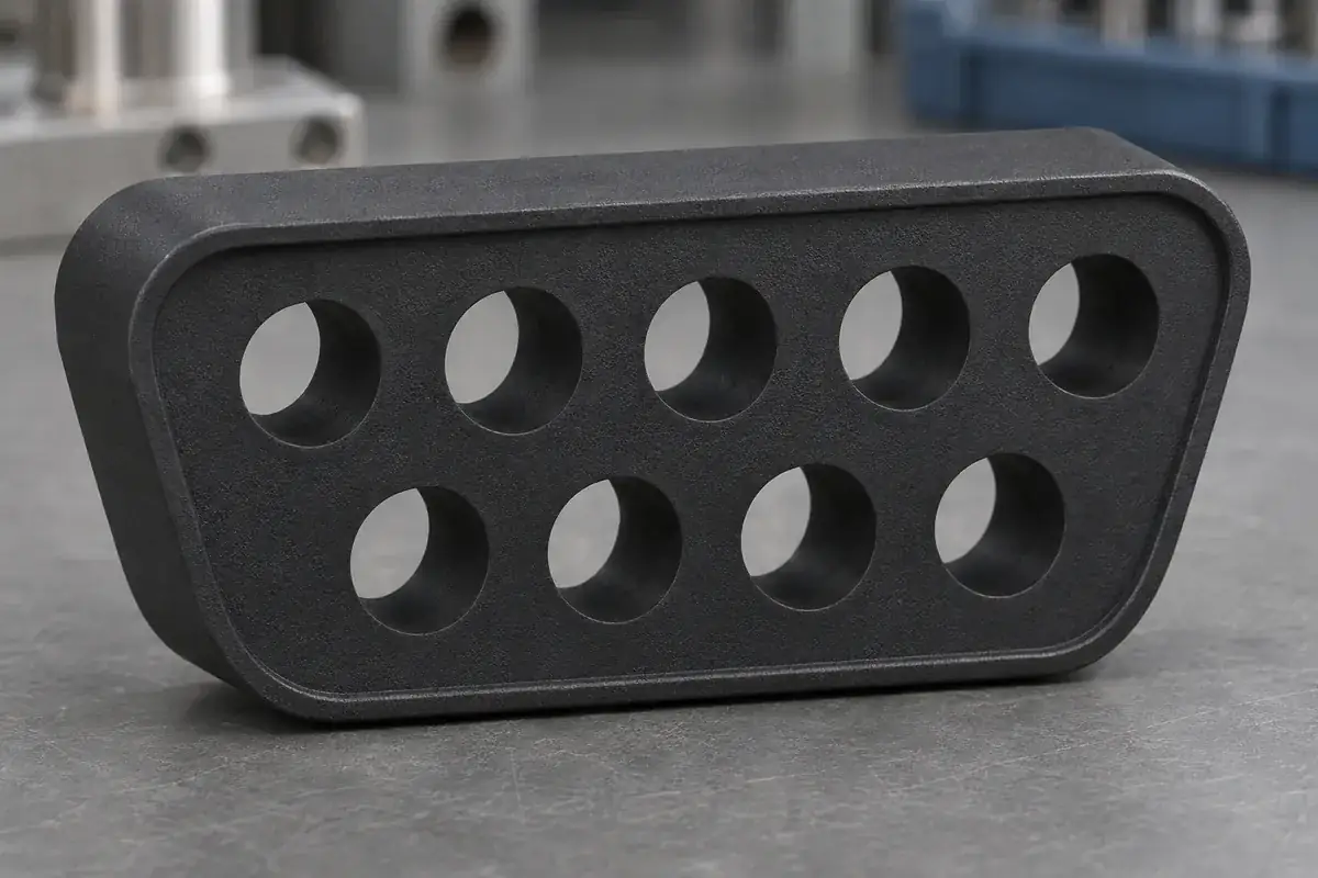
Mating-face cavity pattern
Product design illustration: define the contact pattern and viewing direction relative to the shell and mounting references.
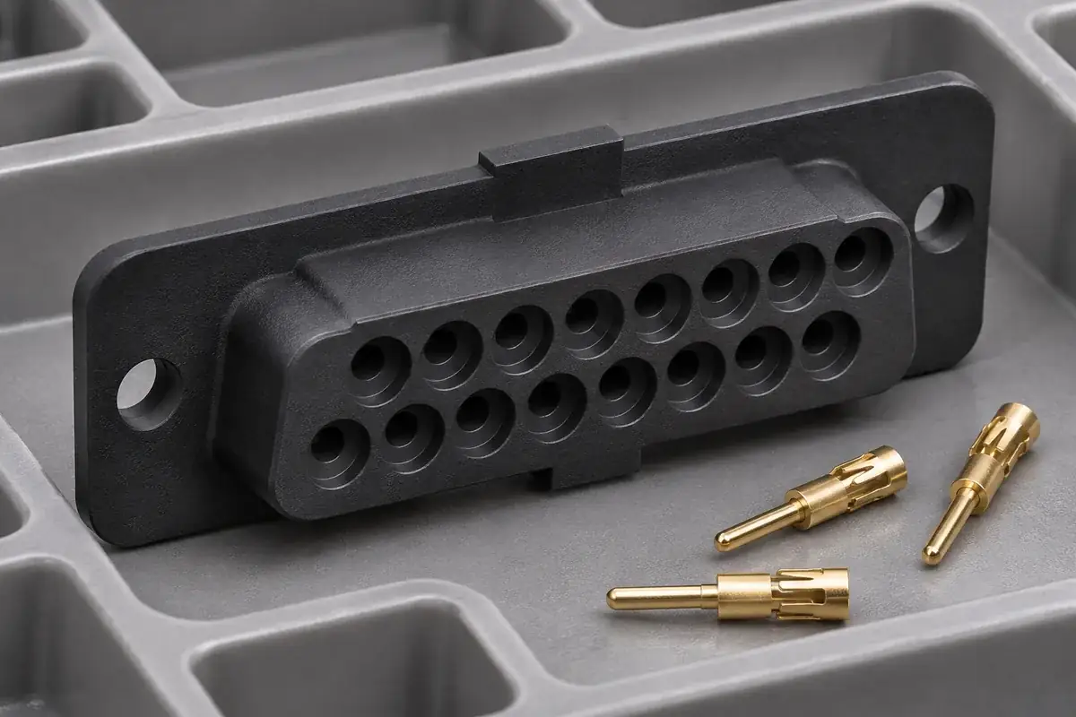
Contact-entry and seating details
Product design illustration: relate each entry, shoulder and retention feature to the selected metal contact.
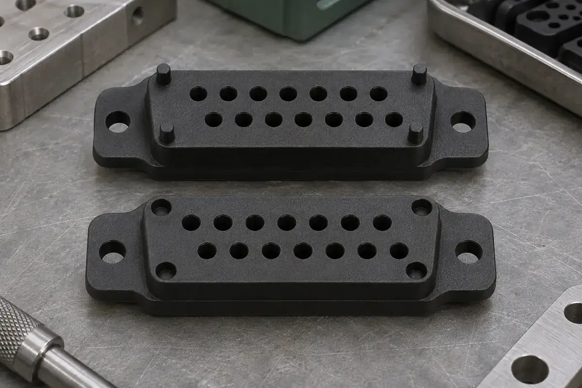
Split-insulator location
Product design illustration: establish how the two molded pieces register before the surrounding assembly retains them.
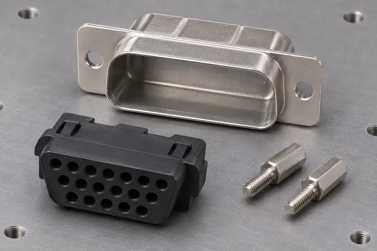
Shell and mounting interface
Product design illustration: coordinate insert seating, shell flanges and mounting hardware without introducing unwanted loading.
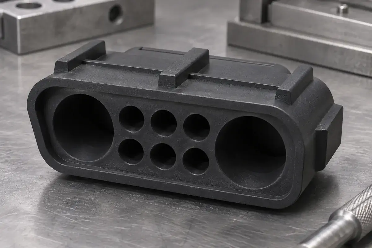
Mixed-contact cavities
Product design illustration: review different contact sizes and their support requirements within one defined layout.
Illustrative configurations. Final specifications follow your approved drawings.
Application fit
Molded insulators around the specified contact and shell construction
A D-sub insulator locates and separates contacts inside a defined shell interface. The hole pattern, contact construction and shell seating features must be considered together. Pin contacts, socket contacts and different termination methods can require different internal geometry even when the mating-face arrangement appears similar.
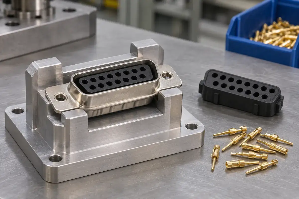
Pin and socket insulating inserts
Molded bodies for drawing-defined contact patterns, with the entry, seating and retention details required by the selected contact. Supply the metal-contact section as well as its front-view outline. The plastic should position the contact while leaving the intended mating and installation actions available.
Standard- and higher-density arrangements
Custom insulators for the specified shell and contact layout. Include the exact drawing or controlled series reference instead of relying on a common connector nickname. Contact size, row arrangement and remaining plastic sections influence molding and assembly access; a shared outer silhouette does not make two inserts interchangeable.
Front and rear insulating components
Separate molded pieces that register through locating faces, pegs, recesses or other defined features. Review their assembly order with the contact-loading and shell-retention operations. The inspection plan should distinguish the dimensions of each empty part from the resulting pattern after the pieces are brought together.
Mixed-contact and application-specific layouts
Insulating bodies with different contact-cavity sizes or additional locating features defined by the customer drawing. Provide each contact type and its installation method. The review considers the separating walls, local support, tooling access and space needed for wire termination or board attachment.
Quote-ready inputs
What to send for a meaningful quotation
Use the same drawing and requirements for every proposal. Mark open decisions explicitly so that a low price does not conceal a different deliverable.
| Area | Please provide | Review before release |
|---|---|---|
| Controlled contact layout | Contact count and arrangement, shell definition, mating-face view and relevant drawing revisions. | Resolve naming and viewing-direction ambiguity before cavity locations are transferred into tooling. |
| Contact construction | Pin or socket drawing, termination type, insertion direction and retention mechanism. | Review cavity entry, seating surfaces and required space around the working contact. |
| Shell and mounting references | Shell section, insert shoulder, flange, jackscrew and equipment mounting details. | Identify the surfaces that locate the insert and those intended to react fastening or mating loads. |
| Material and manufacturing constraints | Approved resin or application requirements, color, exposure and critical surface limits. | Assess small core features, separating walls, parting lines and gate or ejector restrictions. |
| Assembly and inspection | Split-body sequence, shell-retention operation, tooling approach and required reports. | Agree empty-part measurements and completed-assembly observations as distinct checks. |
| Demand and supply format | Trial and repeat quantities, layout variants, packing and approval schedule. | Plan tooling and handling for the agreed component or assembly delivery state. |
From drawing to approval
Connect the plastic drawing to the contact and shell assembly
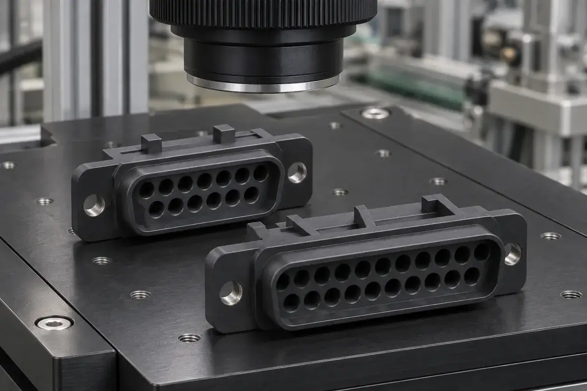
Confirm names, views and revisions
Start with the exact shell and contact arrangement, then identify the mating and wiring views on every drawing. Reconcile the plastic cavity pattern with the metal contacts and mounting references. A common connector name can help communication, but the controlled drawings establish the configuration that is actually quoted and tooled.
Review the molded interfaces
Assess core access, cavity shoulders, thin separating walls and locating faces against filling, ejection and dimensional control. Review how contacts enter and seat, and how split pieces or shell-retention features are brought together. Mark surfaces where flash or vestige could obstruct insertion or shift the assembled pattern.
Evaluate components in their specified state
Inspect empty inserts from the agreed datums, then assemble the identified contacts and shell using the planned sequence. Record the relevant seating, retention and access observations. Complete any electrical, mechanical or environmental evaluation required for the finished connector under its own agreed acceptance plan.
Release the component configuration
Confirm the plastic and mating-part revisions, resin, tooling state, inspection references and packing. Define how changes to contact construction, shell retention or wire routing are reviewed. This gives repeat orders a clear component baseline while keeping subsequent assembly responsibilities visible.
Practical engineering and buying guides
Decisions to make before production
- DB9 vs DE9: Naming a D-Sub Correctly on a DrawingResolve DB9 and DE9 naming before quoting a molded D-sub insulator. Define shell size, contact arrangement, gender, termination and the controlled drawing view.
- Standard vs High-Density D-Sub InsulatorsCompare standard and high-density D-sub inserts through hole layout, plastic webs, contact support, molding access and rear termination space before tooling.
- D-Sub Mating and Wiring Views: Avoid Mirrored LayoutsAvoid mirrored D-sub hole and wiring layouts by defining the viewing face, orientation references, cavity identities and the relationship to assembly tooling.
- Why D-Sub Pin and Socket Insulators Need Different HolesUnderstand D-sub pin and socket cavity differences through contact shoulders, entry guidance, retention and assembly access before copying an insulator design.
- Locating and Assembling a Split D-Sub InsulatorReview two-piece D-sub insulators through locating features, contact capture, joint condition, shell support and inspection references before releasing tooling.
- D-Sub Shell Crimping: Protecting the Plastic InsulatorReview D-sub shell closure through seating, forming support, retaining features and inspection so metal assembly does not damage the molded plastic insert.
- D-Sub Jackscrews and Flanges: Avoiding Off-Axis LoadsReview D-sub mounting ears, jackscrews and panel interfaces together to prevent hardware misalignment from loading the molded insulator during installation.
- D-Sub Solder Cups: Planning Wire and Tool AccessPlan D-sub solder-cup access around wire insulation, termination sequence, tool approach and backshell space while preserving the molded insulator interfaces.
- Mixed-Contact D-Sub Insulators: Different Cavity SizesReview mixed-contact D-sub inserts through large and small cavity envelopes, retention features, insulating paths, tooling access and rear wire routing.
- D-Sub Backshell Strain Relief: Keep Loads off ContactsTrace cable loads through a D-sub backshell, jacket clamp and mounting interface so wire routing and strain relief protect the molded contact insulator.
Related connector manufacturing scopes
Explore empty insulating bodies, components molded around metal terminals and the precision mold inserts used to form them. Each scope has its own drawings and acceptance requirements.
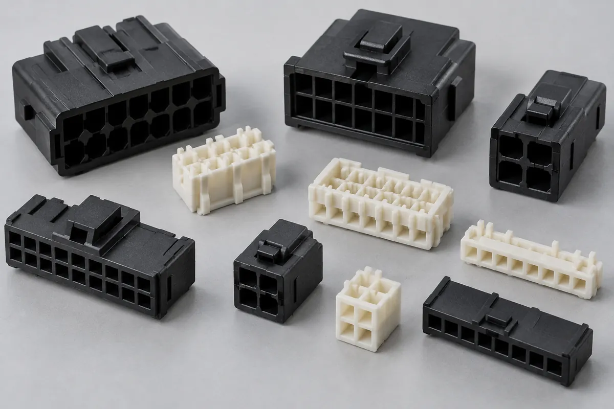
Connector Insulators & Terminal Carriers
Custom molded insulating bodies and terminal carriers. Define terminal interfaces, locating references, exact resin and component acceptance.
Review the application →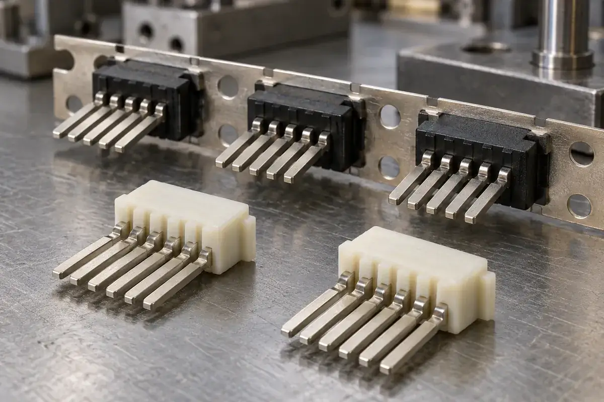
Custom Insert-Molded Connector Components
Custom connector components combining stamped terminals and molded plastic. Review contact location, carrier strips, resin shutoffs, tooling and inspection with FECISION.
Review the application →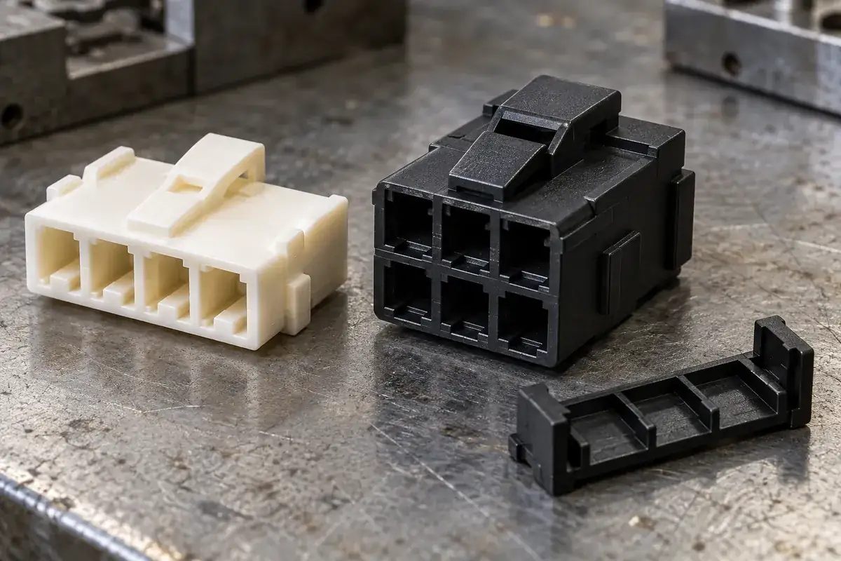
Custom Wire-to-Board Connector Housings
Custom injection-molded wire-to-board connector housings. Review crimp-terminal fit, wire entry, latches, keying and tooling for your plastic components.
Review the application →Before you request a quote
What should a D-sub insulator quotation include?
Send the plastic CAD and drawing, metal shell and contact details, required material, quantities and inspection records. Include the assembly sequence and mounting arrangement. Identify the viewing direction used for the contact pattern so that cavity positions are interpreted consistently.
Is a connector name such as DB9 enough to define the insert?
Use the name alongside the controlled shell and contact drawings. Common usage can differ from a manufacturer shell-size designation. Specify the exact contact arrangement, density and relevant series or drawing revision before developing the plastic component.
Can a pin and socket version share one insulator?
That depends on the chosen contacts and retention construction. Similar mating-face positions can conceal different entry diameters, shoulders or working-contact requirements. Provide both contact drawings so common and distinct plastic features can be reviewed directly.
Can front and rear insulators be molded separately?
Yes, where the assembly is defined as separate pieces. Specify how the parts locate to one another, when contacts are installed and how the final assembly retains them. Include the references used to inspect each piece and the completed cavity pattern.
Can the insert be retained by shell forming or crimping?
Provide the shell section, forming sequence and supporting fixture. The review identifies where the metal moves, where the insert seats and which plastic surfaces may receive load. Agree the final assembly condition before changing a shoulder or shell-retention feature.
Can different contact sizes be combined?
A mixed-contact layout can be reviewed from the specified contact drawings. Include their entry, seating, retention and termination requirements. Different cavity sizes need adequate separating structure and assembly access, with completed-connector requirements addressed for the actual configuration.
What is the role of the backshell cable clamp?
Its intended function and load path depend on the cable and backshell design. Provide the clamp arrangement and wire routing so that cable restraint, conductor access and contact loading can be reviewed together. The insulator drawing alone does not define the completed cable strain-relief performance.
Your next step
Discuss the part with its intended function.
Send the D-sub insert, contact and shell drawings with the intended assembly sequence. We will review the molded interfaces, sample scope and inspection requirements for your custom insulating components.
Explore our connector injection molding service or review other connector components and mold inserts.