
Precision connector components · Made to your design
Custom Card-Edge Connector Housings
Define the board, contact and mounting interfaces around one controlled insertion path.
FECISION coordinates injection molding for drawing-defined card-edge connector housings and related locating components. Share the plastic drawing together with the mating PCB edge, contacts and installed support arrangement. We review the slot, contact cavities, entry features and mounting references to establish a tooling and sample plan for your component.
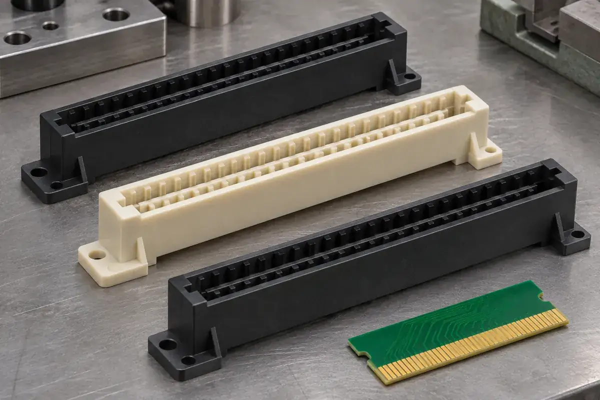
Product details
Explore the board slot, contact cavities and locating features
Product design illustrations show the molded features around a board-edge interface. Your board drawing and selected contacts define the working geometry and acceptance requirements.
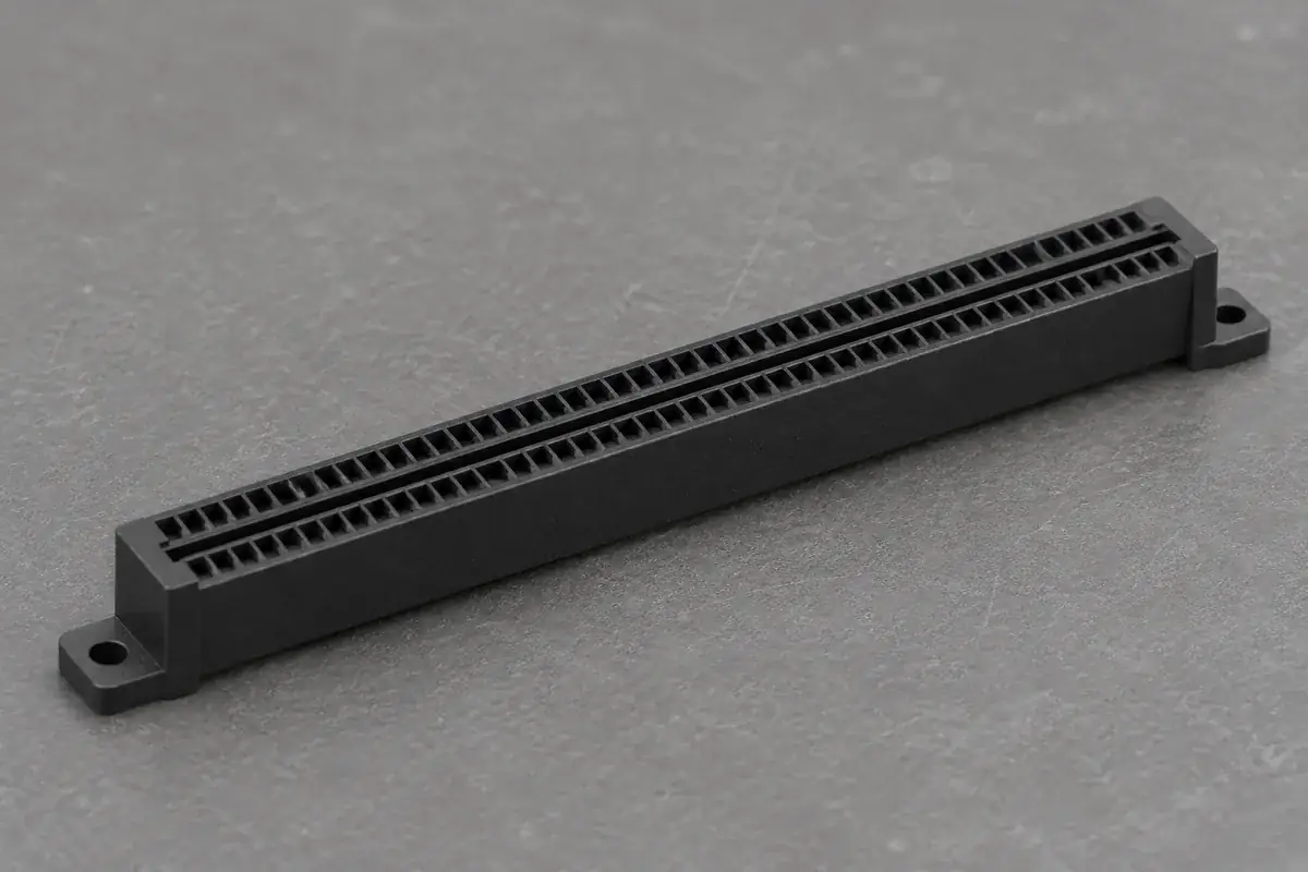
Board slot and contact pockets
Product design illustration: review the molded board-guiding surfaces separately from the metal contact working space.
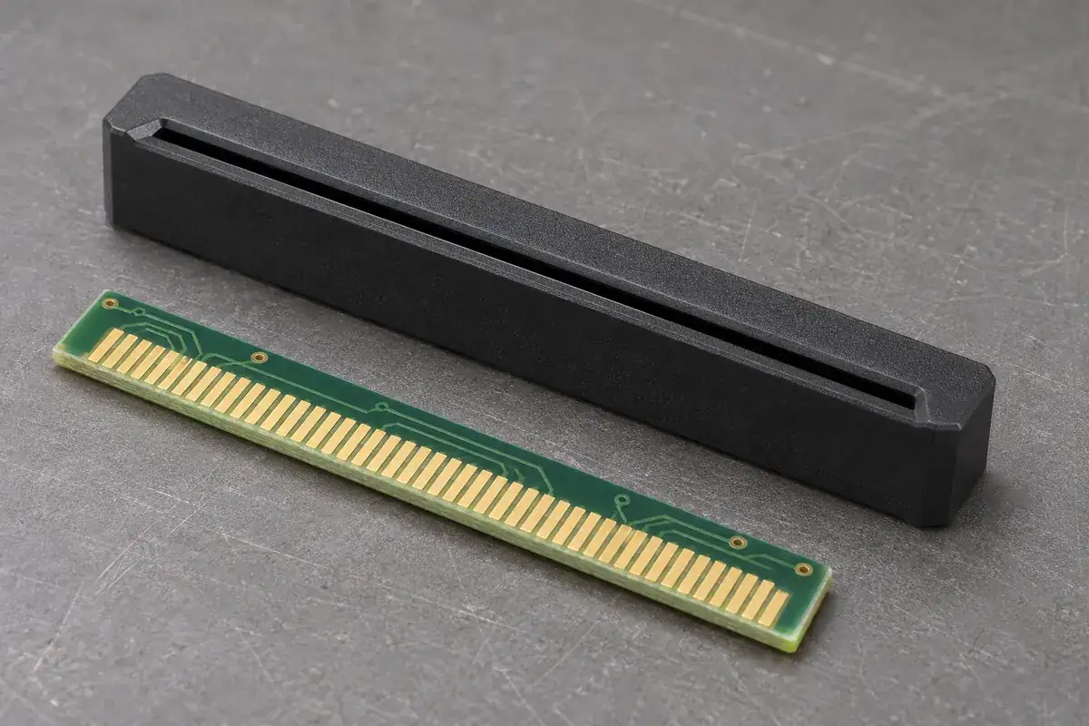
Entry geometry
Product design illustration: coordinate the board bevel and molded entry through the intended insertion path.
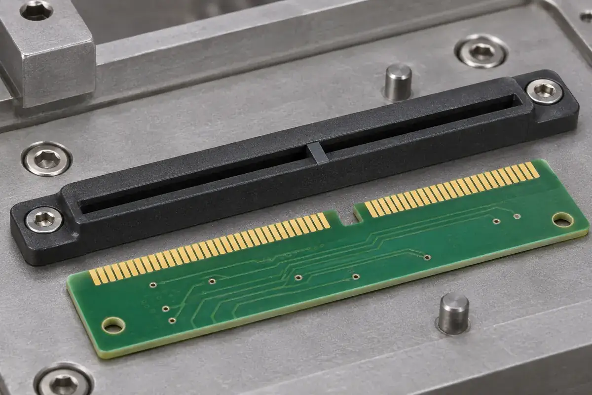
Polarizing features
Product design illustration: locate the key and board notch relative to the contact region and final board position.
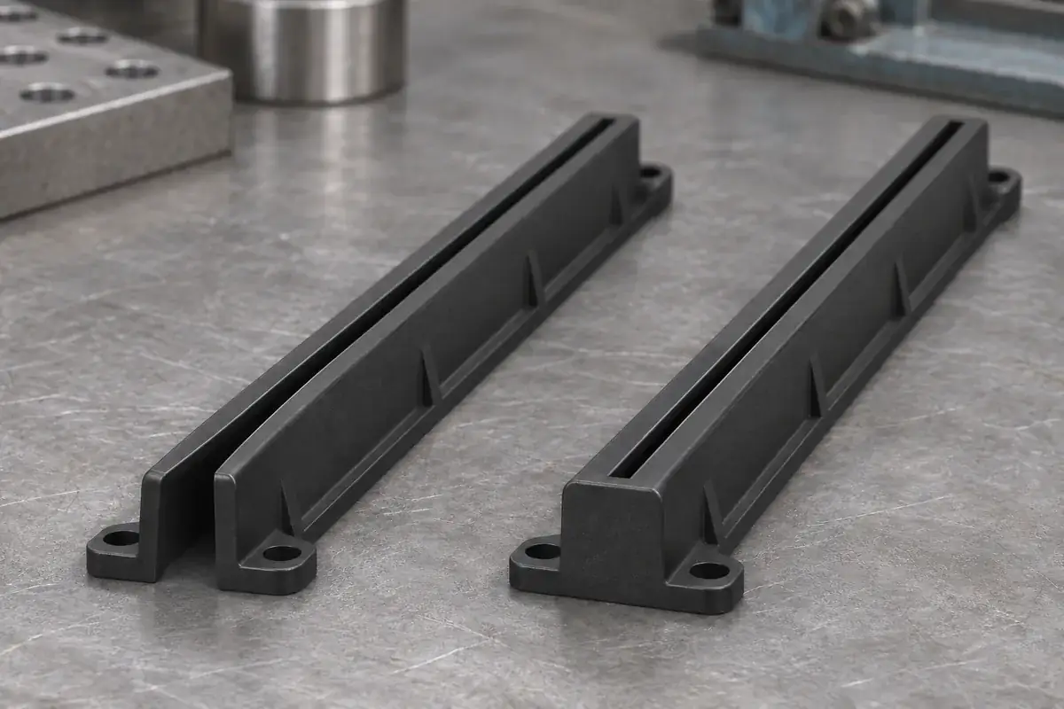
Open and closed ends
Product design illustration: choose the end geometry with the board outline, support and installation route in view.
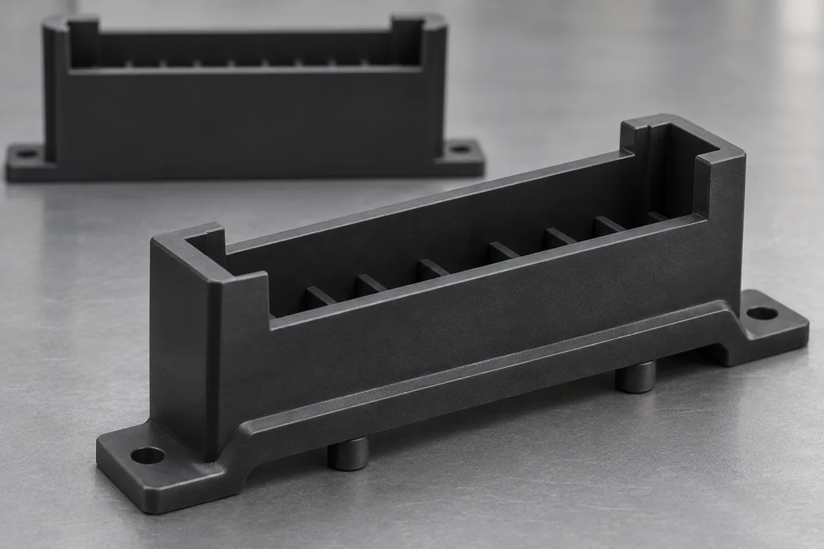
Mounting references
Product design illustration: relate the slot and contact pattern to the surfaces that position the housing in the equipment.
Illustrative configurations. Final specifications follow your approved drawings.
Application fit
Molded housings for a PCB edge that enters the contact system
In a card-edge connection, the board itself forms one half of the interface. Board thickness, edge preparation and contact-pad location therefore belong in the housing review. The molded body guides the insertion and locates the metal contacts, while the equipment mounting and board supports help establish the final relationship.
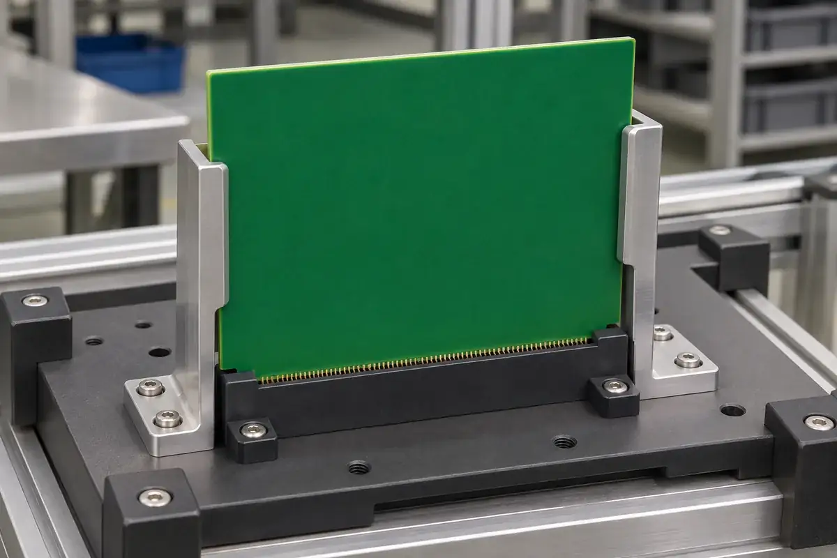
Slotted insulating housings
Longitudinal board slots with drawing-defined contact cavities, separating walls and entry features. Include the intended PCB thickness limits and the contact drawing so that the plastic guidance and contact movement can be reviewed together. The nominal slot opening alone does not define the finished connector performance.
Keyed and end-controlled configurations
Housings with polarizing ribs, board-entry restrictions or controlled slot ends. Supply the mating board outline, notch and pad layout. Review the approach path as well as the seated position, especially where a key can meet the board before the edge reaches its working contact region.
Vertical, horizontal and edge-mounted arrangements
Molded configurations positioned for the actual equipment layout. Show the installation and removal direction, board guides, neighboring components and service access. The choice changes how the board is handled and supported, even where the electrical contact arrangement is similar.
Mounting and locating features
Body feet, shoulders, pegs and other drawing-defined references that locate the connector within a board or frame assembly. Relate those features to the card slot and contact pattern. For a board that engages more than one connector, provide the common mounting references and assembly sequence.
Quote-ready inputs
What to send for a meaningful quotation
Use the same drawing and requirements for every proposal. Mark open decisions explicitly so that a low price does not conceal a different deliverable.
| Area | Please provide | Review before release |
|---|---|---|
| PCB edge definition | Thickness limits, outline, bevel, notch, pad geometry and relevant surface conditions. | Review the complete insertion envelope and the intended board position. |
| Contact and cavity relationship | Selected contact drawing, installation direction, seating features and required movement. | Keep contact support and retention distinct from the space needed for the working contact. |
| Equipment mounting | Housing datums, board guides, supports, fasteners and other simultaneously engaging interfaces. | Identify how the board and connector are located before, during and after insertion. |
| Material and process exposure | Approved resin or candidate requirements, color, soldering and cleaning conditions. | Evaluate material data with the molded geometry and the actual production process. |
| Molding and inspection limits | Critical slots, key positions, cavity flash limits, gate locations and inspection references. | Agree measurements that represent the functional relationships in the assembly. |
| Demand and release plan | Trial quantities, repeat demand, variants, packaging and required approval records. | Plan tooling, sample evaluation and supply format around the intended production route. |
From drawing to approval
Develop the housing around the board and assembly references
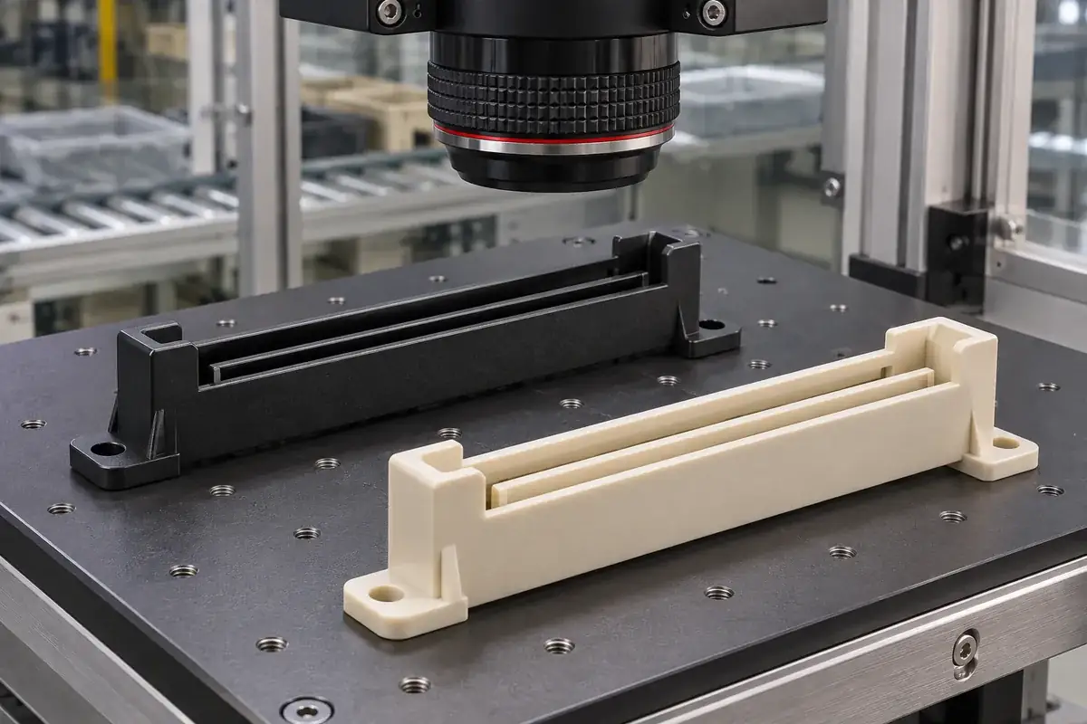
Reconcile the mating documents
Review the plastic drawing, contact definition and PCB edge drawing together. Identify the faces that guide the board, the surfaces that set its final position and the references used to mount the housing. Resolve differences between board outline dimensions and connector drawings before detailed mold development.
Review molding and insertion access
Assess the long slot, small contact pockets, key ribs and mounting features for filling, release and dimensional control. Check how the board approaches and whether its bevel, corners or nearby components can meet the plastic before intended engagement. Include the assembly fixture and service route in this review.
Evaluate representative samples
Inspect the empty molded housing from agreed datums, then assess the selected contacts and a representative board or controlled coupon. Record the board thickness, edge preparation and relevant revisions. Separate a geometric fit observation from the electrical and durability evaluations required for the completed interface.
Release a defined configuration
Confirm the housing drawing, resin, tooling state, PCB interface and inspection plan. Record how guides, supports and fasteners are configured during acceptance. Changes to board thickness, notch position, contact geometry or mounting references can then be evaluated against the approved assembly.
Practical engineering and buying guides
Decisions to make before production
- Card Edge PCB Thickness: More Than a Slot-Fit CheckReview card edge board thickness through the finished PCB, molded slot, spring contacts and installed supports before accepting a connector fit sample.
- Card Edge Bevels and Housing Entries: Different JobsUnderstand how the PCB edge bevel and molded socket entrance affect different stages of card insertion, and review their geometry without masking misalignment.
- Where to Put a Card Edge Polarizing NotchLocate a card edge polarizing notch by reviewing the contact pattern, board outline, connector key and insertion sequence before releasing molded housing geometry.
- Open vs Closed-End Card Edge Connector HousingsCompare open and closed card edge housing ends through board width, lateral location, support and molding requirements before selecting a custom slot structure.
- Supporting Long Cards Beyond the Edge ConnectorReview how card guides, brackets and connector housings share the loads of a long PCB during insertion, installed use and removal without conflicting references.
- Card Edge Contact Wipe and the Insertion StopRelate card edge contact wipe to the gold-finger layout, contact engagement and final insertion stop, rather than using total card travel as the same measurement.
- Debris After Card Insertion: Find the Actual InterferenceInvestigate debris after card edge insertion by separating PCB edge condition, plastic interference and contact wear, then tracing the location and assembly sequence.
- Horizontal vs Vertical Card Edge Connectors: AccessCompare horizontal and vertical card edge layouts through insertion approach, enclosure clearance, guidance and service removal before choosing a molded housing.
- What a Card Edge Fit Coupon Needs to RepresentDesign a useful card edge fit coupon by preserving the board thickness, edge finish, pad pattern, notch and references needed for the specific interface check.
- Aligning a Card with Multiple Edge ConnectorsReview multiple card edge interfaces through shared datums, guide sequence and tolerance accommodation so separate sockets do not demand conflicting board positions.
Related connector manufacturing scopes
Explore empty insulating bodies, components molded around metal terminals and the precision mold inserts used to form them. Each scope has its own drawings and acceptance requirements.
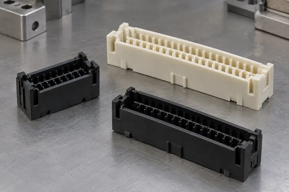
Custom Board-to-Board Connector Housings
Custom molded board-to-board connector housings. Review stack height, alignment, contact cavities, mounting features and inspection with FECISION.
Review the application →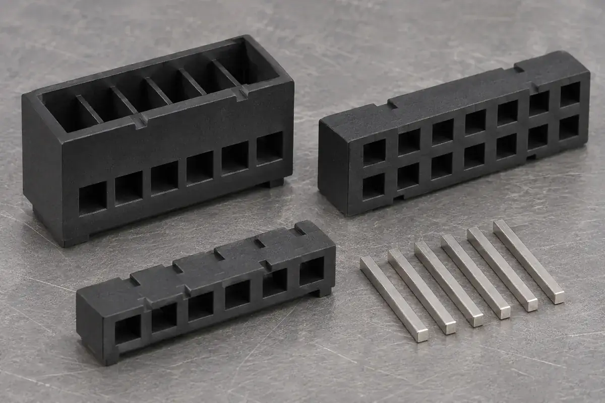
Custom Pin Header and Socket Insulator Bases
Custom molded pin header bases and socket insulators made to drawing. Review pin support, contact cavities, body position, standoffs and assembly requirements.
Review the application →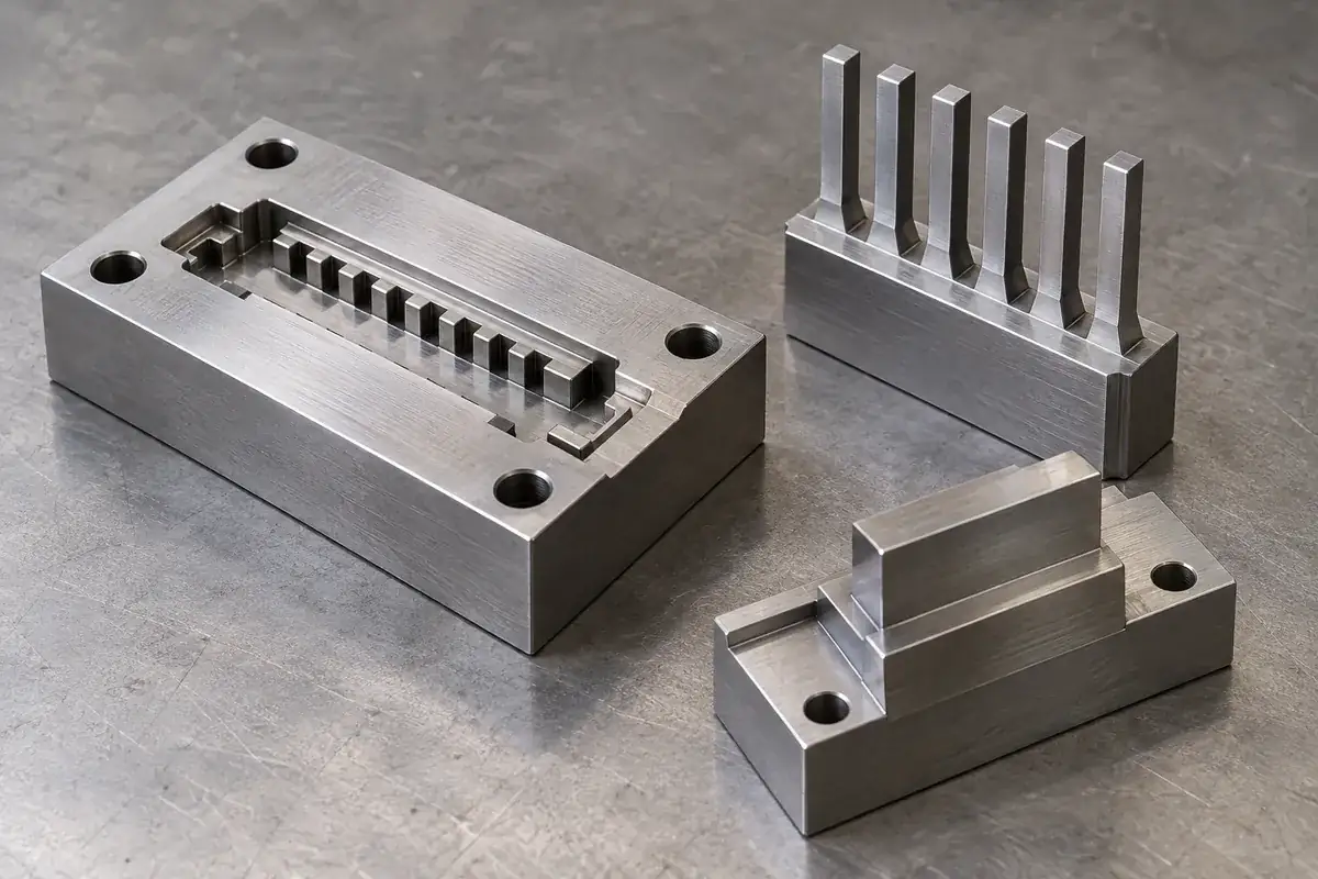
Precision Connector Mold Inserts
Custom steel mold inserts for connector tooling: cavity inserts, thin cores and comb features. Review drawings, locating fits, finishing and replacement scope with FECISION.
Review the application →Before you request a quote
What is needed for a custom card-edge housing quote?
Send the housing CAD and drawing, selected contact geometry and mating PCB edge definition. Include board thickness limits, bevel, notch, pad layout, mounting references, material requirements and quantities. An assembly view helps explain the board supports and access around the connector.
Does a board fitting into the slot establish compatibility?
It establishes only the observed geometric fit in that condition. Contact deflection, pad location, insertion depth and the required electrical performance also depend on the selected contact system and board definition. Agree the relevant completed-assembly checks separately.
Can a housing accommodate several PCB thicknesses?
Provide the proposed thickness ranges and their associated contacts. The molded guidance and the contact working range both need review. A wider plastic opening alone does not establish that one contact arrangement will work for every board thickness.
When is an open-ended slot useful?
An open end can accommodate a board outline or installation route that would otherwise meet an end wall. Review how the board is located and stopped elsewhere, and how the contact region remains correctly positioned. The decision should follow the complete board and mounting arrangement.
Can polarizing keys be added?
Supply the intended board notch and its relationship to the active contact region. Review where the key first meets the board, the remaining plastic sections and the required final position. The board and housing drawings should use a consistent locating scheme.
Should the connector support a long board on its own?
Provide the actual board size, equipment supports and handling conditions. Guides, brackets or other supports may establish alignment and react loads away from the contact interface. Define their position and installation sequence with the housing so they work together.
What should a fit coupon include?
Include the board features relevant to the question being evaluated: controlled thickness, edge preparation, outline, key notch, pad region and locating references as appropriate. Record which conditions the coupon represents. A simplified coupon should not stand in for features it deliberately omits.
Your next step
Discuss the part with its intended function.
Send the card-edge housing drawing with the PCB edge, contacts and mounting arrangement. We will review the molded interfaces and sample requirements for your custom connector component.
Explore our connector injection molding service or review other connector components and mold inserts.