
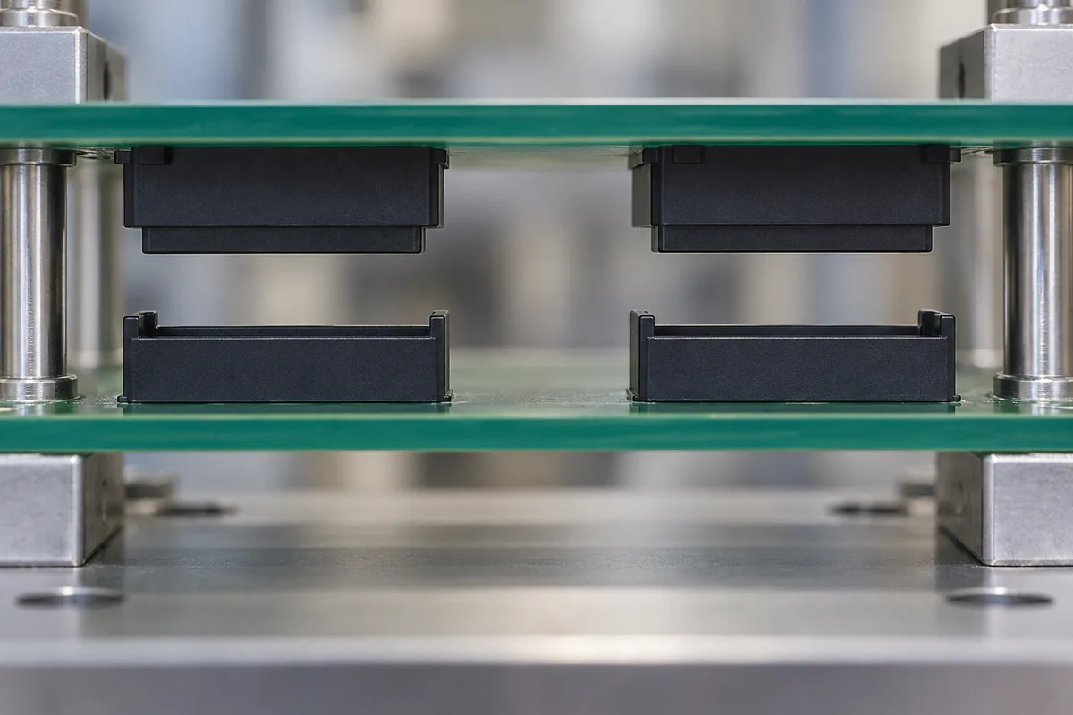
A single mezzanine connector can feel easy to mate on the bench, then become difficult when a second connector is added to the same board pair. Neither plastic housing needs to be visibly defective. The additional pair removes motion that previously allowed the boards to find one another, so small positional differences begin to compete.
The housing design should therefore answer two questions: what guides the first contact between the boards, and what freedom remains while the other interfaces enter? Enlarging every lead-in does not necessarily solve the problem. A part can enter a wide mouth successfully and still bind when its straight guiding surfaces reach the final position.
Product design illustrations accompany the engineering explanations below.
Follow the assembly through its available movements
Before engagement, an unconstrained board can translate and rotate. A guide feature gradually removes some of that freedom. A second guide may remove more. Screws, enclosure rails and external locating pins can constrain the board before either connector becomes involved. The order in which these features engage determines which tolerance relationships the housings actually encounter.
Draw the assembly sequence as several positions rather than one final section. At each position, identify the touching surfaces and the movement still available. A guide that appears beneficial in the final CAD view may arrive too late to protect the contacts. Another may arrive so early that it locks the board before the distant connector can align.
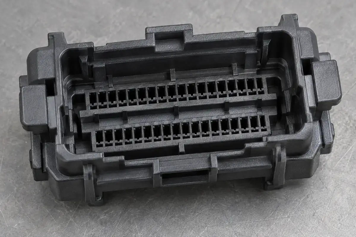
The distance between connectors matters because rotation creates displacement away from the rotation center. A small angular error can produce a larger lateral mismatch at a distant housing. Evaluating only the local cavity position misses this assembly relationship. Place the housing datums in the board coordinate system so the spacing and orientation of each pair can be evaluated together.
Samtec's discussion of multi-connector tolerance stacks explains why additional connector pairs introduce positional relationships absent from a freely aligning single pair. For a custom plastic housing, the useful lesson is to model all simultaneous interfaces rather than assess each nominally identical shell in isolation.
Decide which feature locates and which feature accommodates
A locating feature establishes a repeatable position. An accommodating feature permits movement while preserving the necessary function. Confusing these roles leads to overconstraint: several surfaces all demand an exact location, but their permitted manufacturing variation cannot satisfy those demands simultaneously. The assembly then finds its own compromise through deformation, incomplete seating or damage.
One possible arrangement uses a primary guide to establish position while another permits movement in a selected direction. That does not mean removing control indiscriminately. The permitted motion must remain compatible with the contacts, board supports and final product loads. A relieved plastic surface is not automatically a qualified floating connector mechanism.
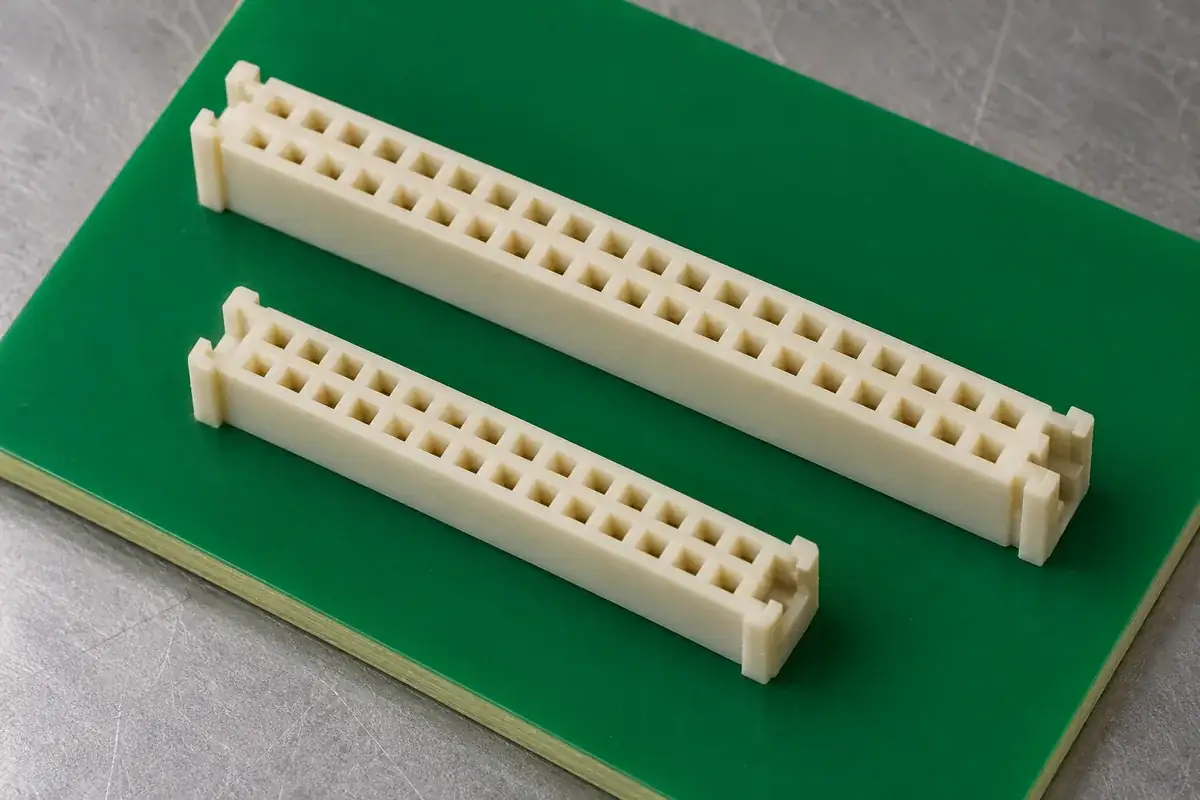
Similarly, clearance between a peg and board hole may help installation but may not produce controlled alignment after soldering or fastening. Once another feature fixes the housing, the original clearance no longer provides useful freedom. Analyze the completed state and the intermediate state separately. The mounting-peg fit guide follows this distinction at the board interface.
A true floating architecture needs an intentional motion path, restoring behavior where required, and approved operating limits. The molded housing may support such a mechanism, but the mechanism also includes contacts or other compliant members. Do not describe a custom shell as floating merely because it has a large opening or a loose mounting feature.
Large lead-ins solve only the first part of the motion
An entrance chamfer converts some axial movement into lateral correction when the approaching part touches it. That correction requires room for one side to move. If the boards are already locked by external hardware, the chamfer instead generates side load. A larger chamfer may increase capture range while leaving this lack of movement completely unresolved.
The transition from lead-in to straight guide wall is equally important. A housing can align at one end and contact the opposite wall at the other end if rotation remains. Long guide engagement offers better orientation control, but it also demands a compatible relationship over more surface length. Select guide length around the expected errors and available stiffness.
Two opposing chamfers can create an appealing funnel in a section drawing while leaving little straight land for stable final location. Reducing that land may permit rocking after mating. The lead-in chamfer article explores this local trade-off; the board-level decision is whether the assembly can use the correction that the chamfer offers.
A mechanical guide outside the connector can sometimes establish coarse alignment before the fine features arrive. It adds components and occupies board or enclosure space, but can move the highest correction load away from delicate housing walls. Its datum relationship to the connectors still belongs in the same tolerance study; external guidance does not erase positioning error.
Test the combination that creates the problem
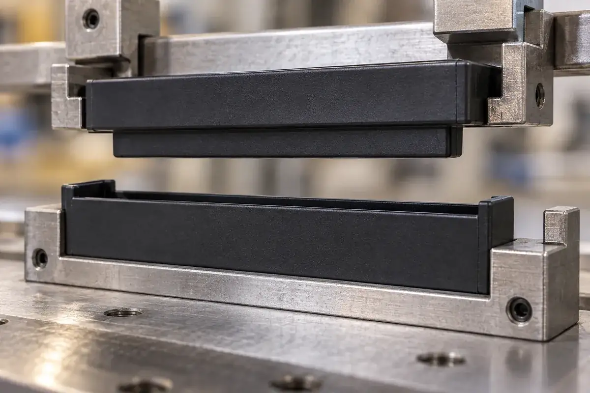
A loose pair of housings proves little about a board carrying several pairs. A useful development fixture includes the relevant spacing, board references and support sequence. It should permit controlled variation in the positions that matter. Otherwise, a perfectly centered fixture can demonstrate only that nominal geometry mates under ideal alignment.
Observe where the first resistance occurs. Contact at the entrance suggests a capture or approach problem. Resistance after partial engagement suggests the straight guide relationship, angular error or an internal obstruction. Resistance that appears only when fasteners tighten points toward the mounting system. These observations help separate mechanisms without immediately changing every cavity dimension.
Use samples identified by cavity and revision so a board-location problem is not confused with a particular molded population. Record the fixture configuration alongside any functional result. A simple pass or fail is difficult to interpret if the assembly has been repeatedly repositioned until it succeeds. The test should preserve the intended production sequence.
When reviewing board-to-board housing supply, include the entire board arrangement and the counterpart geometry. The general insulating-body manufacturing scope establishes how a part is made; successful mezzanine alignment also depends on where the assembly permits motion and where it deliberately removes it.