
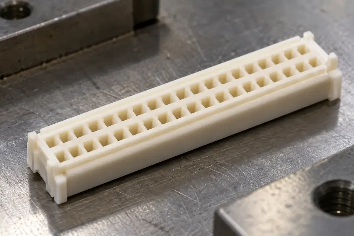
A chamfer at a connector opening is often described as an assembly aid, but that description leaves out the mechanism. The sloping surface converts part of an approaching force into a lateral correction. It works only when the mating part can move in the required direction and the contact occurs on a surface capable of carrying that load.
This matters in a board-to-board assembly because the approaching housing may already be constrained by another connector, a guide post or enclosure hardware. The same chamfer that smoothly aligns a loose pair can generate a side load in a rigid board stack. Its dimensions should follow the assembly motion rather than a standard edge treatment applied everywhere.
Product design illustrations accompany the engineering explanations below.
Define the capture problem before selecting a bevel
Start with the expected approach errors: lateral offset, angular tilt and rotation about the mating axis. These errors present different parts of the housing to the entrance. A side chamfer may help lateral offset while leaving an end corner exposed during rotation. Examine the perimeter and counterpart together instead of judging a single attractive section through the middle.
The first touching surfaces should be suitable guides. If a narrow cavity divider projects beyond the outer guide features, it can receive the initial correction load. A larger chamfer elsewhere will not protect it. Establish the axial order of the guide noses, housing rims and sensitive internal features, including their permitted height variation.
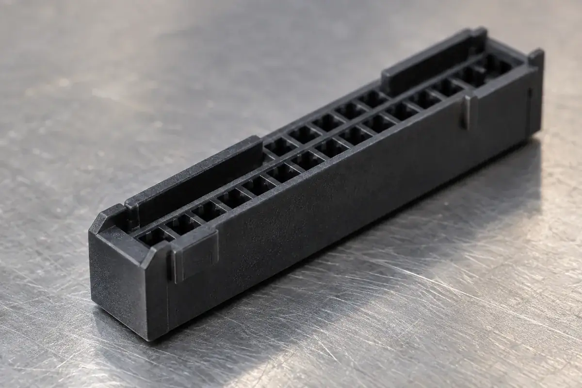
Capture range is not the same as permitted final misalignment. A wide mouth may accept an offset part, but the straight section below must still fit after correction. The available movement should let the pair reach that position. Otherwise, the assembly travels partway and then binds at the transition, which can be mistaken for an undersized opening.
Hirose's DF40 mating guidance emphasizes alignment before continued engagement and warns against excessive force. Those instructions are specific to that connector, but they illustrate why entrance geometry and the mating procedure must be considered together.
Depth, slope and remaining wall form one decision
For a fixed wall envelope, enlarging the chamfer removes material near the entrance. That can improve initial access but reduce the width of the rim that resists handling and assembly loads. A thin lip may flex outward, conceal an interference temporarily, then remain distorted. Evaluate the remaining section and its support rather than approving a chamfer by angle alone.
A longer gentle lead-in provides a gradual correction over more travel. It also occupies axial space that might otherwise be used for straight guidance or engagement. A shorter steep transition concentrates correction into less travel. Neither arrangement is universally better; the choice depends on available height, friction, stiffness and the force that the assembly can safely apply.
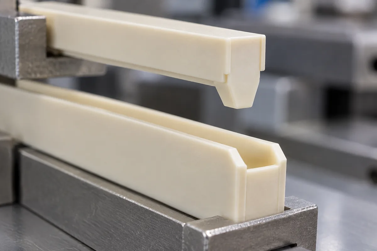
Two chamfered members do not automatically double useful capture. Their contact can migrate as they approach, and a narrow edge can slide along another edge before either guide reaches stable contact. Review the pair as moving solids. The nominal gap between two bevels in a final section says little about the loads during that transition.
At the end of the chamfer, preserve the required straight guide land. Too little land can leave the seated pair free to rock or rotate. Too much can make the assembly sensitive to bow and angular differences along the housing. The guide length and clearance must be assigned together with the board-level alignment scheme.
Manufacturing details change the working entrance
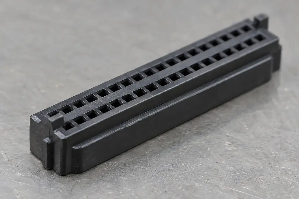
A nominal chamfer can be altered by flash, gate vestige, an edge radius or a parting-line mismatch. These deviations matter most where the counterpart first touches. Identify that working perimeter in the drawing and tooling review. A generic cosmetic surface callout may miss a small obstruction that has little visual impact but consistently disrupts entry.
Draft is another distinct geometry. It helps release the molded part and changes the wall position along the draw direction. A drafted inner guide may have its smallest clearance away from the entrance. Measuring only the mouth can therefore approve a part that still interferes deeper inside. Define the controlling sections and the intended transition into each.
Sharp mathematical intersections also become finite edges in steel and plastic. A controlled radius may improve durability, while an uncontrolled radius may reduce a polarization stop's effective overlap. Coordinate the chamfer with adjacent keying features. The correct approach should be guided, while an incorrect approach should encounter the intended blocking surfaces.
Local wall thickness affects how reliably the entrance shape can be produced and retained. A heavy rim attached to a thin wall can introduce a different cooling response from the nearby body. The molding review should consider that transition together with filling and ejection. Increasing thickness solely to strengthen a lip can create a new dimensional problem elsewhere.
Evaluate the approach that the production process will use
A hand-held sample can often be wiggled into place until the guides succeed. An automated fixture may have a fixed path and no equivalent motion. Development checks should reproduce the intended approach, support and permitted compliance. If a small repositioning is necessary, decide whether it belongs in the process or requires a change to the interface.
Observe whether the first resistance is symmetric. Contact at one corner can indicate angular or rotational error, while simultaneous resistance on two sides may indicate insufficient clearance. Do not infer a force limit from these observations alone; use them to locate the mechanism and define the next controlled evaluation with the connector assembly team.
Inspection can include entrance profile, the position of the chamfer relative to the mounting references, and the straight section below it. A functional master can evaluate combined entry, but it should have a defined geometry and condition. An arbitrary mating sample may be unusually forgiving or unusually restrictive, obscuring which feature needs correction.
For custom board-to-board housings, provide the mating motion and counterpart alongside the plastic drawing. The general insulator manufacturing review covers the component's resin and toolability; a useful lead-in is approved by how it captures, corrects and hands over to the final guide relationship.