
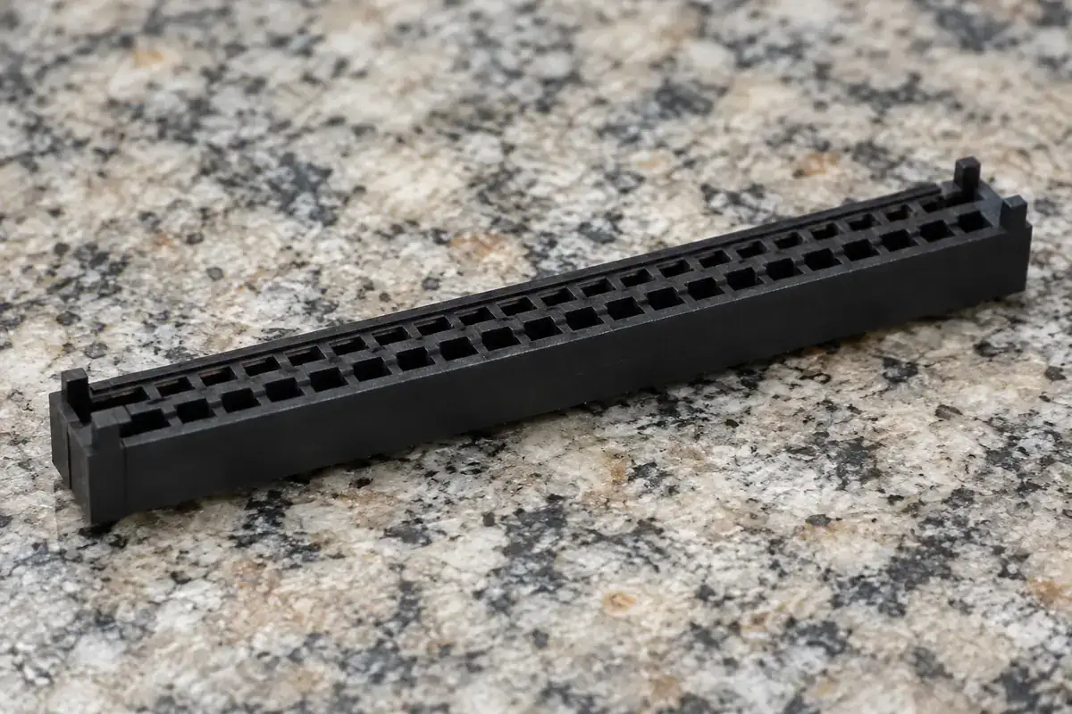
A long connector housing can rock on a surface plate yet assemble correctly under its intended supports. Another can appear flat on the same plate while its guide walls twist enough to interfere with the mating half. The word warpage is therefore only a starting description. The engineering question is which distorted relationship affects the assembly.
For a mezzanine housing, seating feet, contact cavities and guide walls may each respond differently to molding and later exposure. A single maximum gap does not describe all of them. Inspection should distinguish the free shape of the part from the shape it takes under its approved mounting condition, then connect each requirement to a function.
Product design illustrations accompany the engineering explanations below.
Name the deformation that changes the interface
Bow along the length can change how the ends and center meet a board or counterpart. Twist can place diagonally opposite corners at different heights. Local wall movement can narrow one section of an opening without strongly affecting the overall base. These conditions may coexist, but they should not be collapsed into one vague instruction to keep the housing flat.
Choose the relevant reference surfaces first. A cosmetic outer wall may not be a functional datum. The mounting feet may establish the board relationship, while the guide land controls mating and the cavities control contact location. Measure each relationship from the references that the assembly uses, rather than from whichever surface is easiest to place on a table.
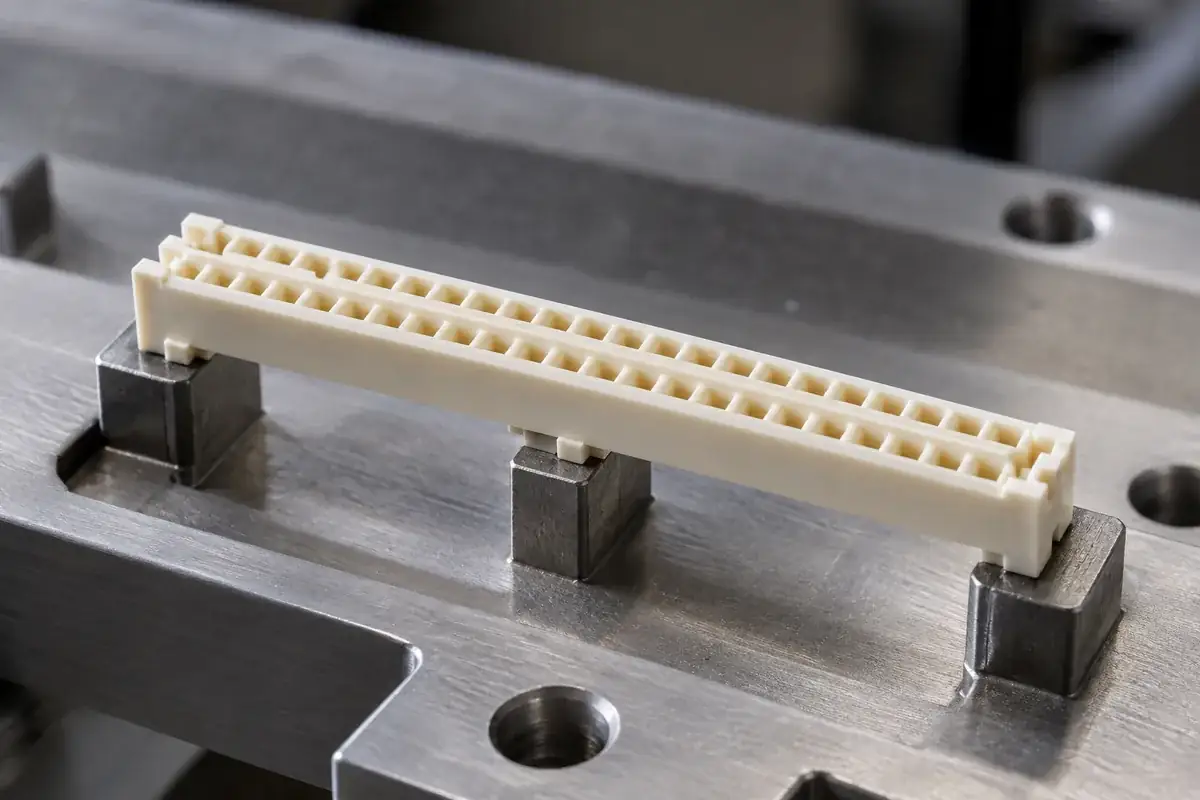
A broad surface plate can contact an unintended projection and tilt the entire part. A fixture with defined supports can avoid that ambiguity, but it introduces its own restraint. The support arrangement, contact force and orientation should therefore be recorded with the result. Without those details, two inspectors may measure different physical states while both report warpage.
Hirose's DF40 catalog specifies a board-warpage condition using stated references. It concerns that connector and board system, not a general housing allowance, but demonstrates why a deformation limit needs an explicit location and reference scheme.
Understand why the free state and mounted state differ
A slender housing can change shape under a relatively small fixture force. If the inspection nest pushes it flat, the resulting dimensions describe the constrained state. That may be appropriate for an assembled requirement, but it should not be presented as a free-state measurement. The constraint must reproduce the intended mounting rather than merely make inspection easier.
Conversely, a free-state deviation may matter even if mounting can flatten it. The force needed to achieve that shape must be carried by the board, contacts or attachments. If the design did not assign that load path, the assembly may be using a vulnerable feature to correct the plastic. Evaluate the required restraint as well as the resulting geometry.
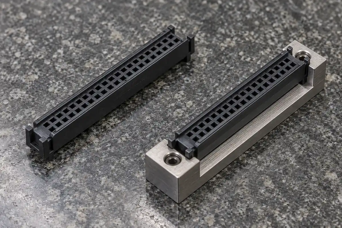
Supports can also create distortion. Uneven standoffs or a warped board may force an initially acceptable housing into an unfavorable shape. A failed mating check after installation is not automatically evidence that molding caused the problem. Compare the housing before and after mounting, preserving the same references wherever possible, to identify where the relationship changes.
The board stack-height chain adds a vertical constraint to this review. A bowed housing between two fixed boards can experience different engagement along its length. A single height reading at the center cannot establish the conditions at both ends. Select measurement positions that correspond to the actual guide and contact regions.
Review geometry and process together
Long thin walls, local thick sections and asymmetric features can respond differently as the molding cools. Gate position, flow direction, material reinforcement and ejection can interact with that geometry. These are reasons to investigate the process and design together, not grounds for predicting a specific deformation from a photograph or resin-family name.
Adding a rib can increase stiffness but also change local material distribution and cooling. Making every wall thicker can create further differences while consuming space needed for the mating half. A useful design change targets the functional deformation and its likely mechanism. Verify the result on identified samples rather than assuming that added material always improves straightness.
A narrow guide wall may be influenced by a nearby pickup bridge or key. These secondary features can connect regions that otherwise move independently. When changing them, inspect the guide profile and cavity relationship again. The pickup-surface guide explains why assembly handling features belong in the same geometry review.
Specimen condition is also relevant. Time after molding, conditioning and any agreed thermal process can affect the state being assessed. The correct sequence depends on the selected material and product requirements. Record it rather than mixing freshly molded samples with differently conditioned parts and interpreting their spread as one stable production population.
Use combined fit without losing diagnostic detail
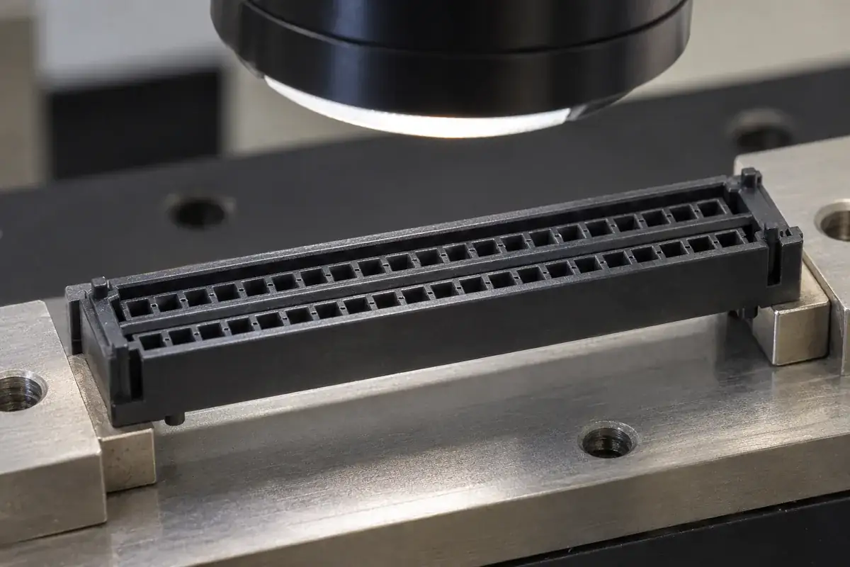
A mating master can show whether the housing enters and seats under defined conditions. It combines several dimensions, making it useful for function but less specific for diagnosis. If a sample fails, local measurements should help distinguish bow, twist, profile interference and position error. Otherwise, repeated tooling adjustments may chase the wrong surface.
The master itself must have a controlled geometry and support condition. A compliant counterpart can mask a housing deviation, while an unusually rigid master can reject behavior the actual assembly permits. Neither is inherently wrong if it represents the agreed acceptance boundary. State that boundary and preserve the master configuration with the result.
Inspect by cavity and revision during development. Similar overall shape can conceal a cavity-specific guide or seating difference. Keep the free-state observations, mounted measurements and combined-fit results linked to the same samples. That makes an apparent contradiction useful evidence about restraint rather than a reason to discard one of the measurements.
For custom mezzanine connector housings, agree which surfaces must be straight, where they are referenced and how the part is supported. The general insulator manufacturing review helps define the molded component. Functional warpage acceptance then connects its shape to the board, counterpart and forces that establish the assembled condition.