
Precision connector components · Made to your design
Custom FPC and FFC Connector Housings and Actuators
Define the cable interface and actuator motion before turning a small plastic part into a production drawing.
FECISION reviews custom injection-molded housings and actuators for FPC and FFC connector designs. Share the plastic drawings with the cable end, contact arrangement and mating component geometry. We assess cable guides, support ears, pivot or slider interfaces, latch features and inspection references as one connected molding scope. Material, tooling, quantities and acceptance are agreed for the specific design.
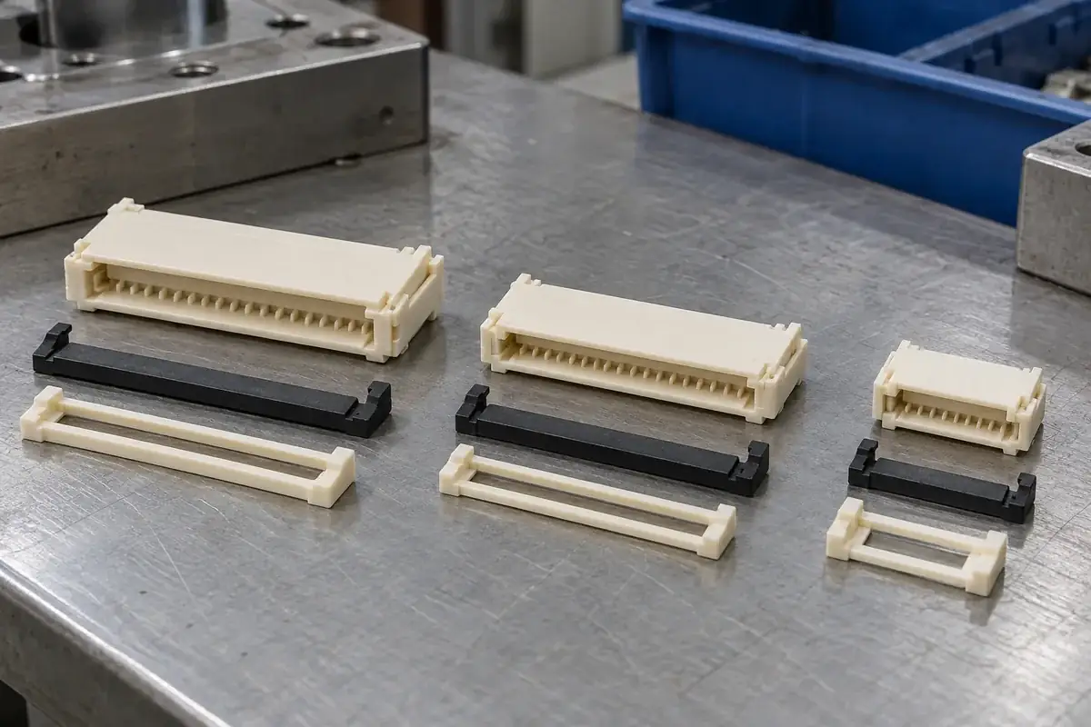
Product details
Cable guides, moving interfaces and supported molded features
Product design illustrations show the plastic components separately so the housing, actuator and counterpart relationships can be reviewed clearly.
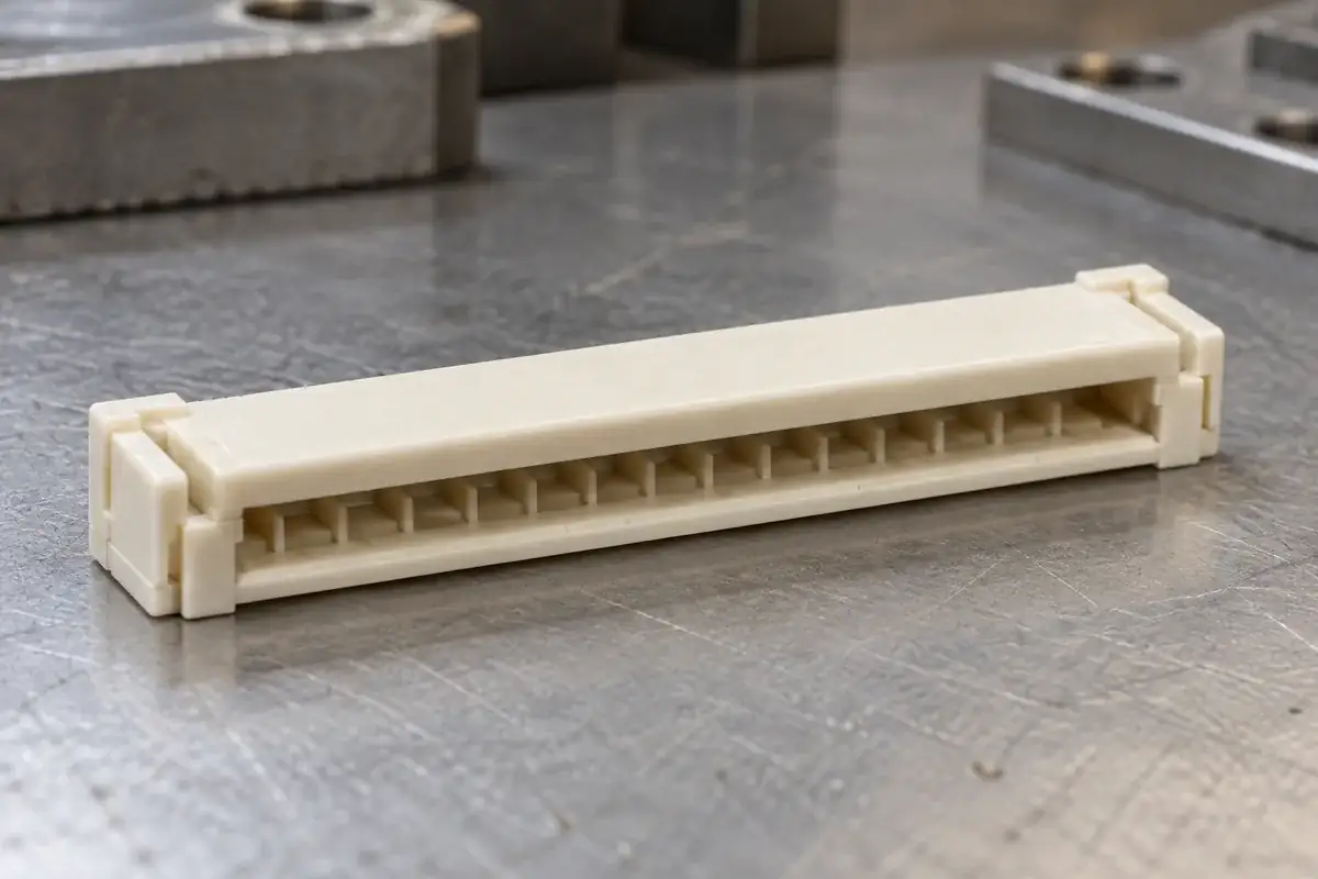
Cable-entry housing
Product design illustration: review the entry mouth, guide walls and local clearances against the specified cable construction.
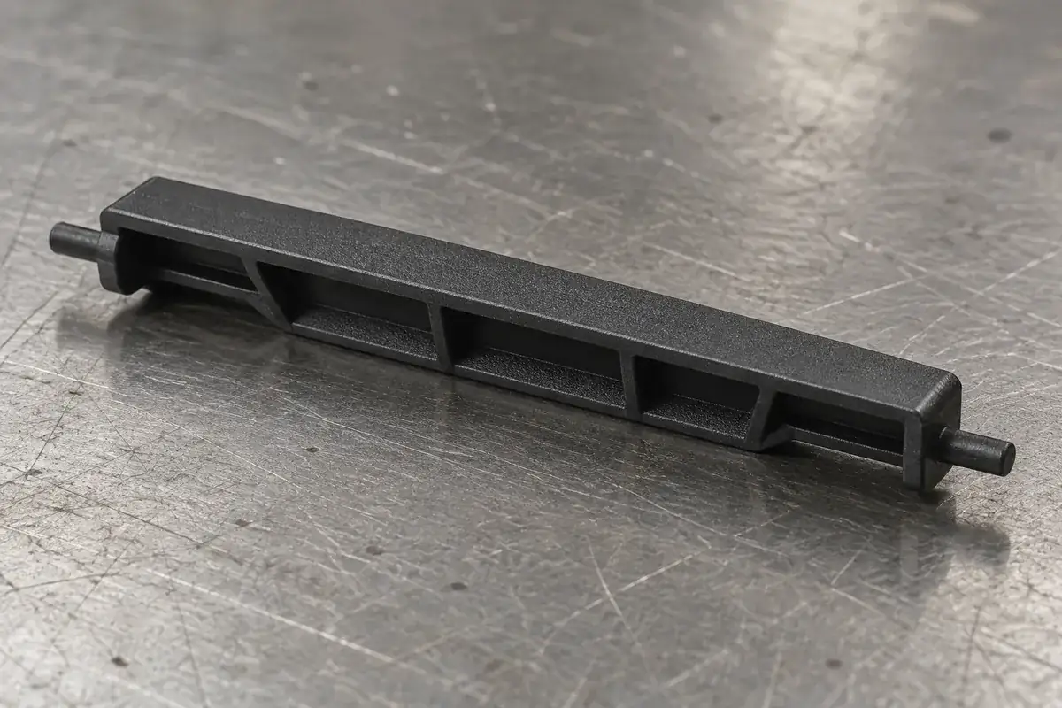
Flip-actuator interfaces
Product design illustration: define the pressure surfaces, end supports and working motion together with the mating housing.
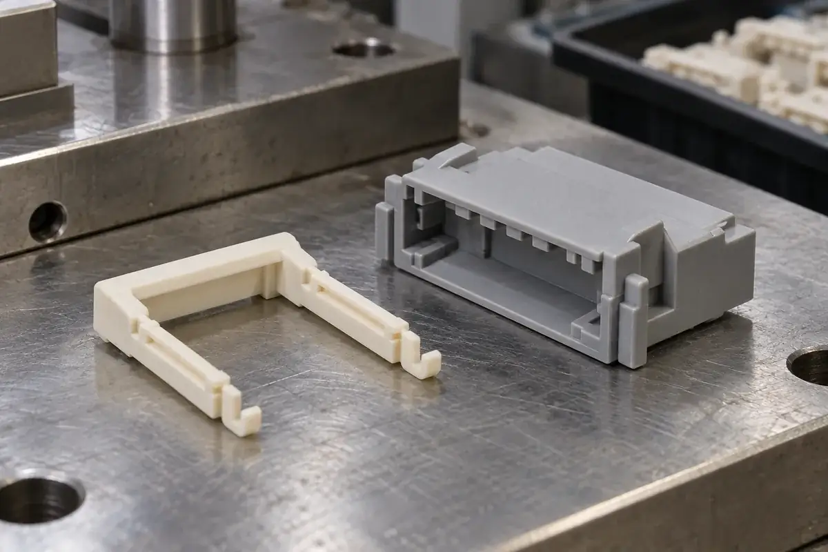
Slider-actuator geometry
Product design illustration: coordinate side rails, approach clearance and retaining features through the full travel.
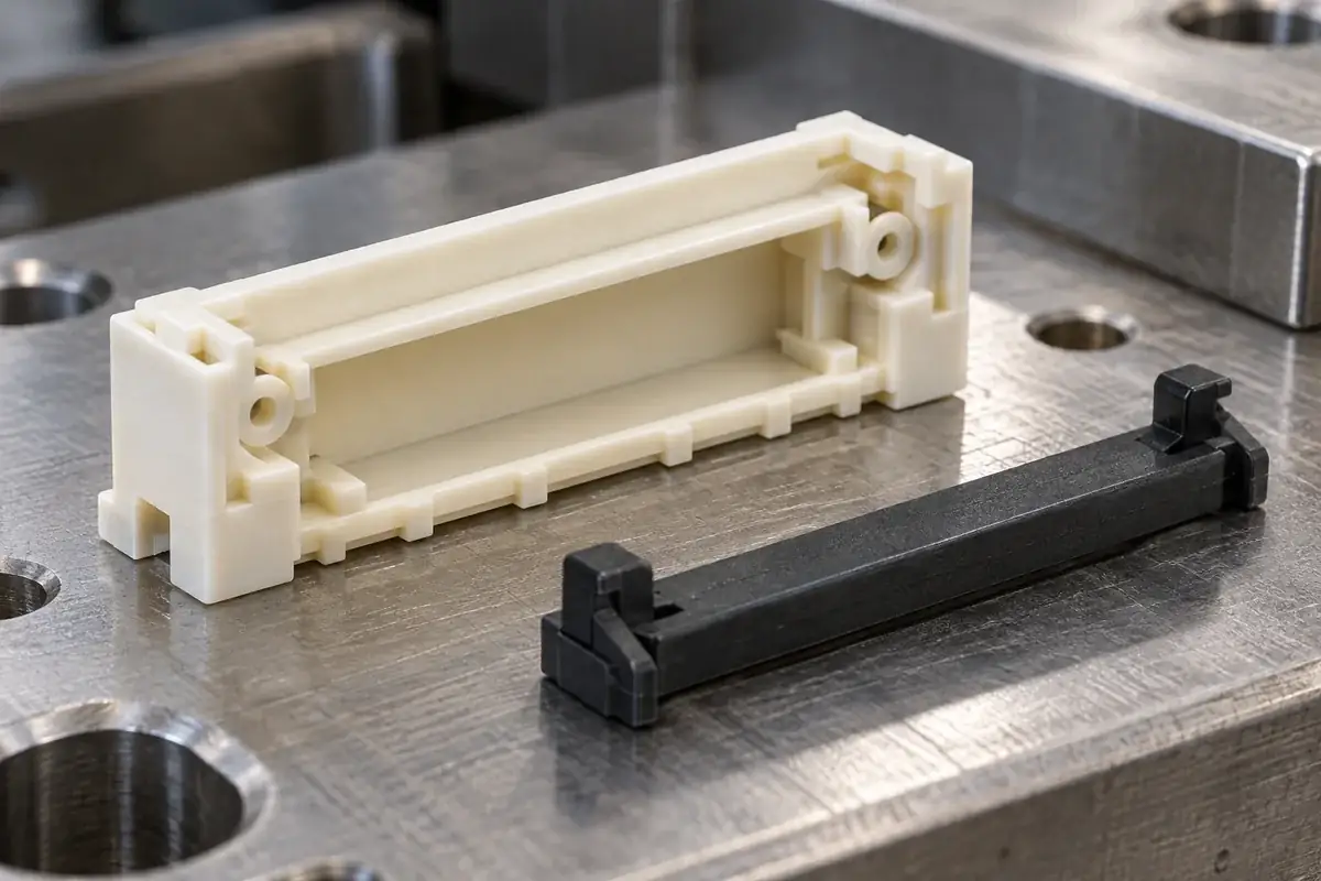
Housing support features
Product design illustration: distinguish cable seating, pivot support and travel stops as separate functional relationships.
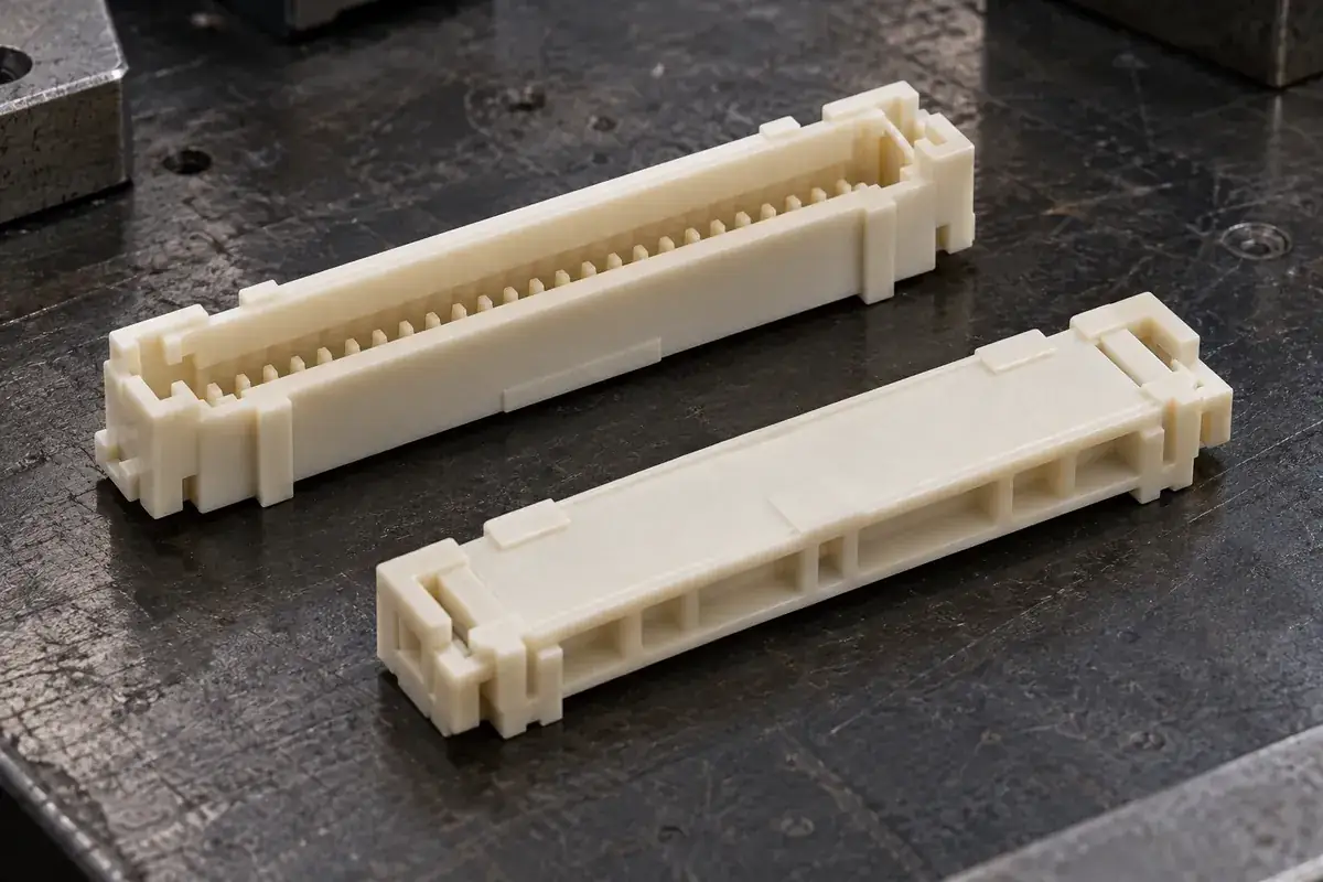
Locating and release surfaces
Product design illustration: establish assembly datums and permitted molding witnesses before the tool layout is finalized.
Illustrative configurations. Final specifications follow your approved drawings.
Application fit
Custom plastic components for a defined connector assembly
A housing guides and supports the connector interfaces; an actuator controls a mechanical state. Their drawings need the intended cable, contacts and assembly context even when the quotation covers only molded plastic. The relevant dimensions and operating conditions are established for the actual configuration.
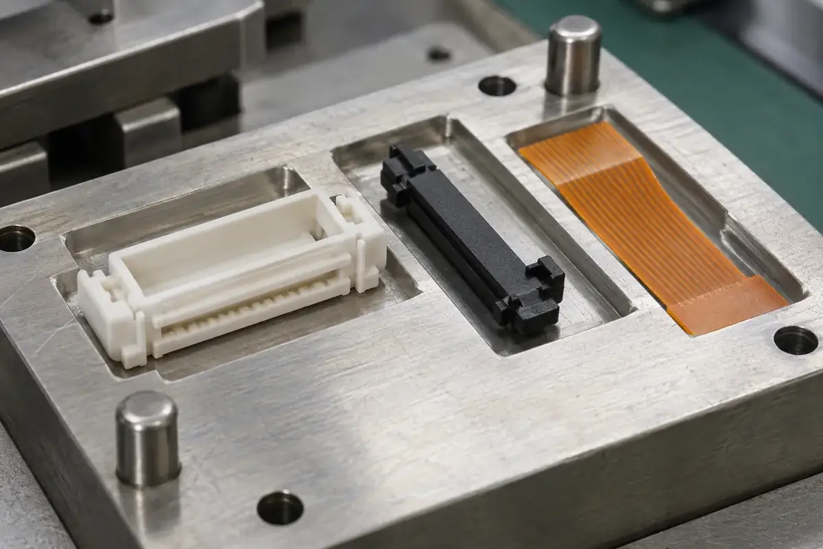
FPC and FFC connector housings
Empty molded bodies with cable entrances, guide walls, separating ribs, seating features and actuator supports. Review the local cable stack and contact orientation alongside slot geometry. Long walls, narrow openings and support ears need a tooling route that preserves the intended interface after molding and release.
Flip-style actuators
Custom moving bars with drawing-defined pressure surfaces, pivot features, stops and retaining details. The review connects the loose molding to its installation sequence and operating motion. Housing support and the location of applied force matter as much as the actuator outline when assessing assembly and inspection.
Sliding actuators and related locating parts
Custom sliding frames, guide elements and connector-adjacent plastic parts made to an agreed component definition. Review rail alignment, end-to-end travel and latch engagement together. The selected connector architecture determines the required cable seating and closing sequence; these are not universal properties of an FPC or FFC label.
Quote-ready inputs
What to send for a meaningful quotation
Use the same drawing and requirements for every proposal. Mark open decisions explicitly so that a low price does not conceal a different deliverable.
| Area | Please provide | Review before release |
|---|---|---|
| Component definition | Housing and actuator CAD, controlled drawings, revision, critical dimensions and component quantities. | Identify functional surfaces, permissible design changes and whether parts must be interchangeable across cavities or matched as sets. |
| Cable and contact interfaces | Cable-end drawing, local stack and stiffener details, conductive-face orientation, contact geometry and seating references. | Verify the intended insertion path, local clearances and closed-state relationship without assuming a generic cable-thickness range. |
| Actuator motion and assembly | Open and closed states, pivot or rail geometry, latch and stop details, installation sequence and operating supports. | Separate component installation from cable mating and identify the surfaces intended to receive force during each operation. |
| Material and exposure | Exact resin grade where selected, color, reinforcement, documentation needs and actual thermal or environmental exposure. | Review grade-specific molding behavior and mechanical requirements for housing and actuator separately, then assess their interface. |
| Tooling and visible surfaces | Gate, parting-line, ejector and finish restrictions, cosmetic zones and functional edge conditions. | Coordinate long-slot core support, mold release and ejection with cable guides, pivot seats and assembly datums. |
| Acceptance and supply | Inspection features, sample state, counterpart revisions, report needs, packing method and planned order quantities. | Agree dimensional and visual acceptance, any controlled assembly checks, sample traceability and the evidence needed for release. |
From drawing to approval
Connect the plastic drawing to assembly and inspection
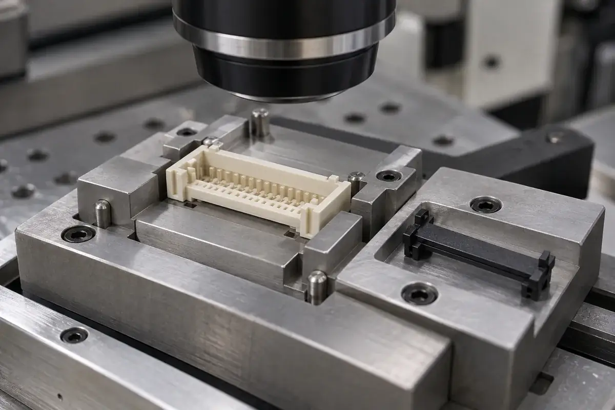
Establish the assembly references
Review the housing, actuator and relevant cable or contact definitions at compatible revisions. Identify what locates the cable, what guides actuator motion and what establishes the stopped and retained states. Record unresolved interfaces before they become assumptions embedded in the tool.
Review resin and molding geometry
Assess the selected material with wall transitions, narrow slots, pivots, rails and latch roots. Discuss forming direction, core support, gate and ejection locations against the functional surface map. Any proposed geometry change should preserve the agreed mating and operating relationships.
Evaluate identified molded samples
Inspect the relevant dimensions and edge conditions in the agreed support state. Where assembly trials are included, use identified counterpart revisions and a defined operation. Record what the check establishes so a fit observation is not mistaken for complete connector qualification.
Approve the controlled supply configuration
Connect the accepted drawing, material, cavity identification and inspection plan to the production release. Agree handling and packing that protect loose pivots and latch arms. Changes to the cable interface, material or working geometry should trigger review of the related acceptance evidence.
Practical engineering and buying guides
Decisions to make before production
- FPC and FFC Connector Housings vs ActuatorsUnderstand how FPC and FFC housings guide the cable while actuators control closure, and why their molded interfaces need separate acceptance criteria.
- FPC Cable Thickness and Connector Housing FitTrace FPC cable thickness, stiffener position and housing clearance through insertion and closure without assuming a universal cable or slot dimension.
- FPC Connector Top and Bottom Contact OrientationConnect FPC pad orientation to housing references, cable routing and assembly checks, including why rotating a connector view can cause design mistakes.
- Flip-Lock vs Slider FPC Actuator DesignCompare the motion, support and molding interfaces of flip-lock and slider FPC actuators, with practical trade-offs for access and assembly control.
- FPC Actuator Pivots and End StopsReview pivot support, actuator overtravel and end-stop contact in molded FPC connectors, with a focus on load paths and meaningful inspection references.
- FPC Cable Insertion Depth and Housing StopsExplain how cable leading edges, housing stops and contact regions define FPC insertion depth, and how to distinguish full seating from a misleading closure.
- FPC Actuator Travel and Latch EngagementSeparate actuator travel, stop position and latch overlap in FPC connector parts, then diagnose skew, interference and incomplete engagement methodically.
- Mold Release for Long FPC and FFC Housing SlotsReview long cable-slot cores, housing wall support, draft and ejection together so molding changes preserve the functional FPC and FFC interface.
- Assembly Fixtures for FPC Housings and ActuatorsDesign FPC component assembly fixtures around functional datums, supported force paths and observable seating so tooling does not conceal part variation.
- Cosmetic vs Functional Inspection of FPC PartsClassify FPC housing and actuator marks by location and effect, then connect visual checks, dimensional inspection and assembly evidence without overclaiming.
Related connector manufacturing scopes
Explore empty insulating bodies, components molded around metal terminals and the precision mold inserts used to form them. Each scope has its own drawings and acceptance requirements.
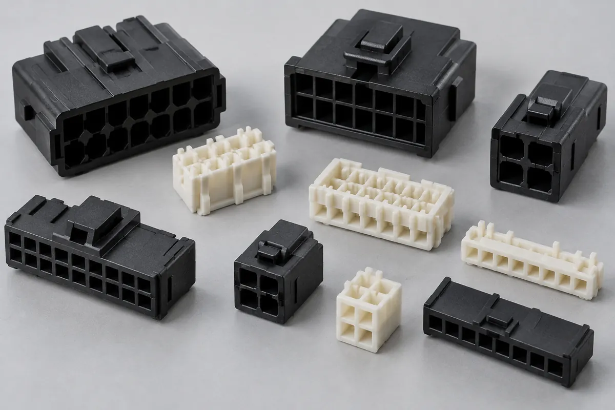
Connector Insulators & Terminal Carriers
Custom molded insulating bodies and terminal carriers. Define terminal interfaces, locating references, exact resin and component acceptance.
Review the application →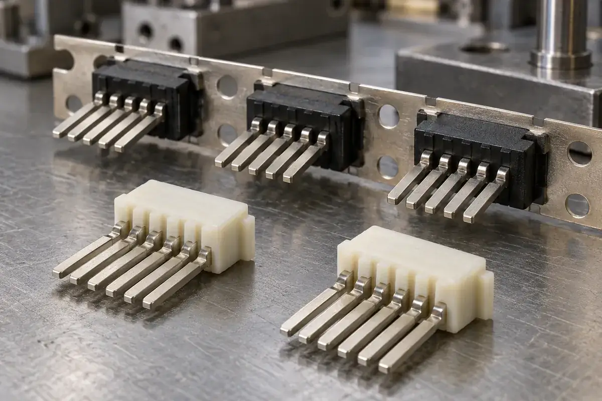
Custom Insert-Molded Connector Components
Custom connector components combining stamped terminals and molded plastic. Review contact location, carrier strips, resin shutoffs, tooling and inspection with FECISION.
Review the application →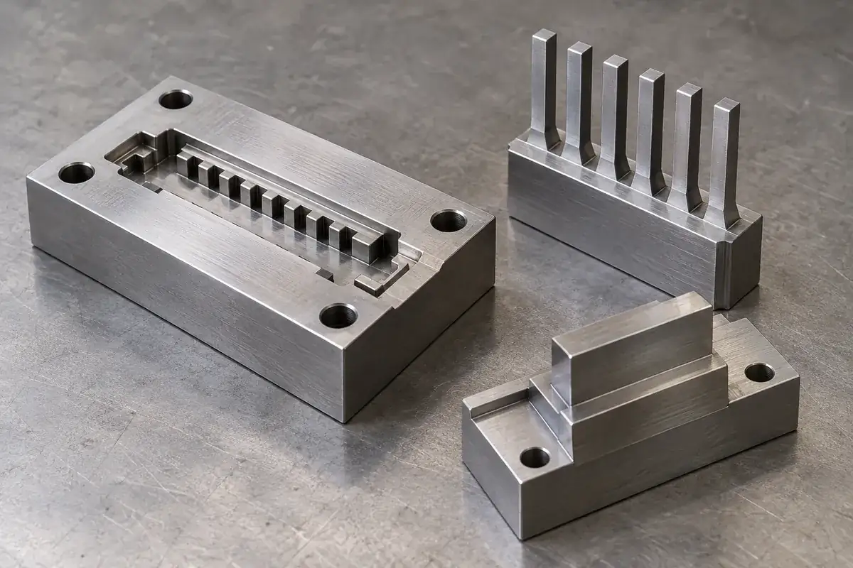
Precision Connector Mold Inserts
Custom steel mold inserts for connector tooling: cavity inserts, thin cores and comb features. Review drawings, locating fits, finishing and replacement scope with FECISION.
Review the application →Before you request a quote
Are these complete FPC or FFC electrical connectors?
This page covers custom molded plastic housings, actuators and related defined components. Contacts, cable supply, complete assembly and electrical testing can only be included through an explicit agreed scope. The product design illustrations show interface concepts rather than catalog connector ratings.
Can an FPC housing also accept FFC?
Compatibility depends on the selected connector design and the actual cable end, including local thickness, reinforcement, pad orientation and seating geometry. Share the approved cable definition. Similar pitch or outside width alone does not establish interchangeability.
Can you mold both flip and slider actuators?
We can review drawings for either mechanism as a custom molding inquiry. Feasibility depends on the working geometry, material, tool access, assembly method and acceptance requirements. The actuator and mating housing should be reviewed together before confirming the manufacturing scope.
Which resin should the housing and actuator use?
Provide the approved grades where available. Otherwise, review the actual mechanical duty and exposure with the part geometry. A stationary housing and a moving latch may have different priorities; a resin-family name does not establish reflow compatibility, operating life or a complete connector rating.
What dimensions or tolerances can you guarantee?
Tolerances are agreed after reviewing the specific drawing, material, tooling and measurement method. Define slot references, pivot or rail relationships and the required sample state. There is no universal cable thickness, pitch or latch-clearance range implied by this custom component page.
How should visual and functional acceptance be separated?
Identify cable guides, stops, pivots, latch faces and datums as functional zones, then define cosmetic areas and viewing conditions. Dimensional inspection, controlled assembly trials and complete connector testing answer different questions and should have separately agreed criteria.
Your next step
Discuss the part with its intended function.
Send the housing and actuator drawings together with the cable end and mating interfaces. We will review the molded features, material, tooling and acceptance requirements so the quotation reflects the components and evidence your assembly needs.
Explore our connector injection molding service or review other connector components and mold inserts.