
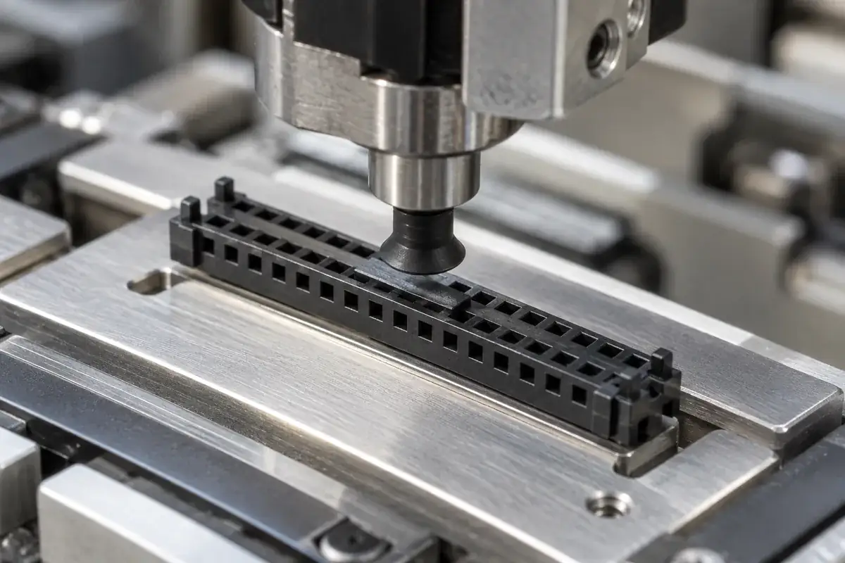
A connector housing can be easy to hold between fingers and difficult for an automated nozzle to handle. Its upper face may consist mainly of open cavities, narrow rails and asymmetric guide features. Adding a small flat pad can help, but only if the nozzle can reach it, establish a usable seal and lift the part without creating an unstable moment.
The handling surface is therefore an assembly interface, not spare cosmetic space. Its location connects the molded geometry to the nozzle, carrier pocket and placement process. For custom board-to-board housings, that interface should be designed before the tool is finalized, especially when an attractive low-profile shape leaves little uninterrupted area on top.
Product design illustrations accompany the engineering explanations below.
Choose a pickup region that the nozzle can actually use
A usable region needs a compatible surface shape and enough access around the intended nozzle. Nearby walls can interfere before the nozzle reaches the pad. An open slot crossing the contact area can prevent the expected seal. Evaluate the nozzle envelope against the complete housing, including the guides and keys that project above its body.
The pickup location also affects balance. A nozzle placed far from the part's effective center can lift one end first or promote rotation during motion. The correct location depends on the delivered configuration: an empty housing and a populated connector may have different mass distributions. Specify which item the placement process handles rather than assuming they behave identically.
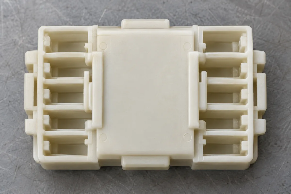
A larger pad can improve access for a range of nozzles, but it consumes space and may cover a cavity or obstruct mating. A thin bridge may preserve the opening below while adding flexibility. A thick bridge may be more rigid but alter the molded section. The pad should be evaluated as part of the housing's manufacturing and functional geometry.
Molex's SlimStack floating-series datasheet includes a metal cap to facilitate pick-and-place handling. That example shows why a dedicated handling feature can be useful; its cap design and operating conditions are specific to that connector family.
Compare an integral pad with a removable cap
An integral molded pad avoids a separate component and installation step. It remains part of the housing throughout its lifecycle, so it must coexist with contact assembly, mating and service access. If the pad spans a cavity, verify the space below it and the tools needed for later operations. A handling improvement should not block the connector's primary function.
A removable cap can provide a broad pickup surface without permanently occupying the mating envelope. It introduces a different sequence: install, transport, pick, place and remove. Each step needs a compatible retention and release method. A cap that detaches during acceleration is ineffective; one that requires excessive removal force can disturb the placed component.
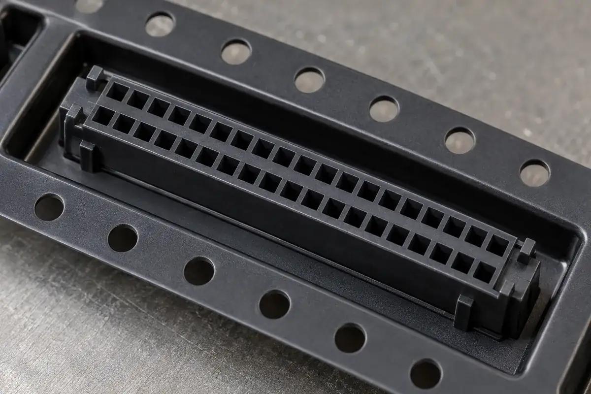
The cap's retention features should contact robust regions of the housing. Clipping onto a thin guide lip can change its shape or leave damage in the mating entrance. Repeated installation during development may also behave differently from the intended single production cycle. Define the sequence and inspect the surfaces that the cap actually loads.
Removal access matters after placement. A cap that is easy to remove from a loose connector may be trapped between nearby board components. The product assembly layout should include the removal tool or motion. If a cap remains through another manufacturing step, its material and retention need review for that step rather than being assumed suitable.
Surface quality means more than appearance
A pickup pad may look flat while containing a gate witness, recess or parting-line step in the nozzle contact region. These features can affect sealing or make the nozzle sit at an angle. Identify the usable contact zone on the drawing so tooling and inspection focus on the surface that the machine relies on.
Texture is another process-dependent choice. A finish that is acceptable on the housing exterior may not suit the selected nozzle interface. Do not specify a universal polished surface without understanding the equipment. Agree the relevant contact condition and evaluate it using the intended nozzle and handling method, including any permitted variation in nozzle position.
The pad's height relative to adjacent features determines approach clearance. Its height relative to the housing seat affects the placement reference if the machine uses top contact position. A warped bridge or an uneven cap can therefore introduce a handling error even when the housing's mounting feet are correct. Keep these reference chains visible in the assembly review.
Changes to the pad can affect filling and cooling because it adds material or redirects local flow. A bridge connected at both ends can also restrain neighboring walls differently from an open design. Review the resulting guide and cavity geometry during sample evaluation. Handling features should not be exempt from the functional warpage review.
Connect the housing to its delivery presentation
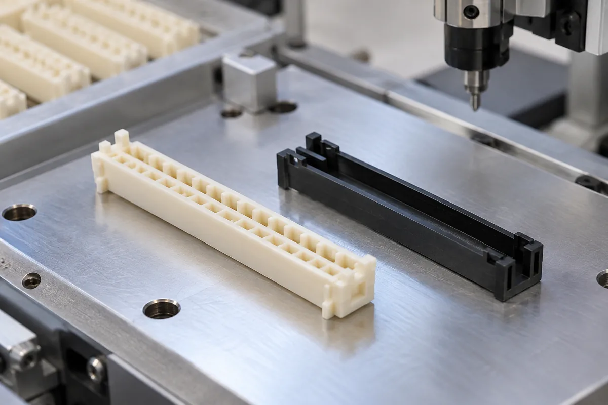
A well-designed pickup pad cannot compensate for a carrier pocket that lets the housing roll or sit at inconsistent angles. The packing definition should establish orientation, support and clearance for nozzle access. Protect the guide lips and pegs from becoming unintended support points. The presentation must remain compatible with the actual empty or populated component being supplied.
Placement evaluation should distinguish failure to pick from loss during movement and failure to seat. These events suggest different mechanisms. A leaking contact region differs from an unstable center of mass, and both differ from a tight mounting-peg fit. Recording the event location prevents an unnecessary redesign of the entire housing.
Use the intended nozzle, pocket and motion sequence for development evidence. Successful manual vacuum pickup demonstrates a limited interaction, not production yield. Likewise, a photographed part under a nozzle is an illustration of the arrangement, not proof of a validated automated process. Acceptance should be based on the agreed equipment and component configuration.
For custom board-to-board connector housings, include the pickup surface and packing orientation in the manufacturing discussion. The general insulating-body scope covers the molded part; an effective delivery definition also explains how that part is presented, lifted, placed and released in the next operation.