
Precision connector components · Made to your design
Custom Insert-Molded Connector Components
Bring the terminal drawing and the plastic body together before the mold is built.
FECISION coordinates custom connector-component manufacturing around stamped metal contacts and the plastic molded around them. Share the terminal, carrier-strip and component drawings so stamping, insert location, mold shutoffs and inspection can be reviewed as one manufacturing sequence. The resulting part may be supplied on its carrier strip or separated, as agreed for your next assembly operation.
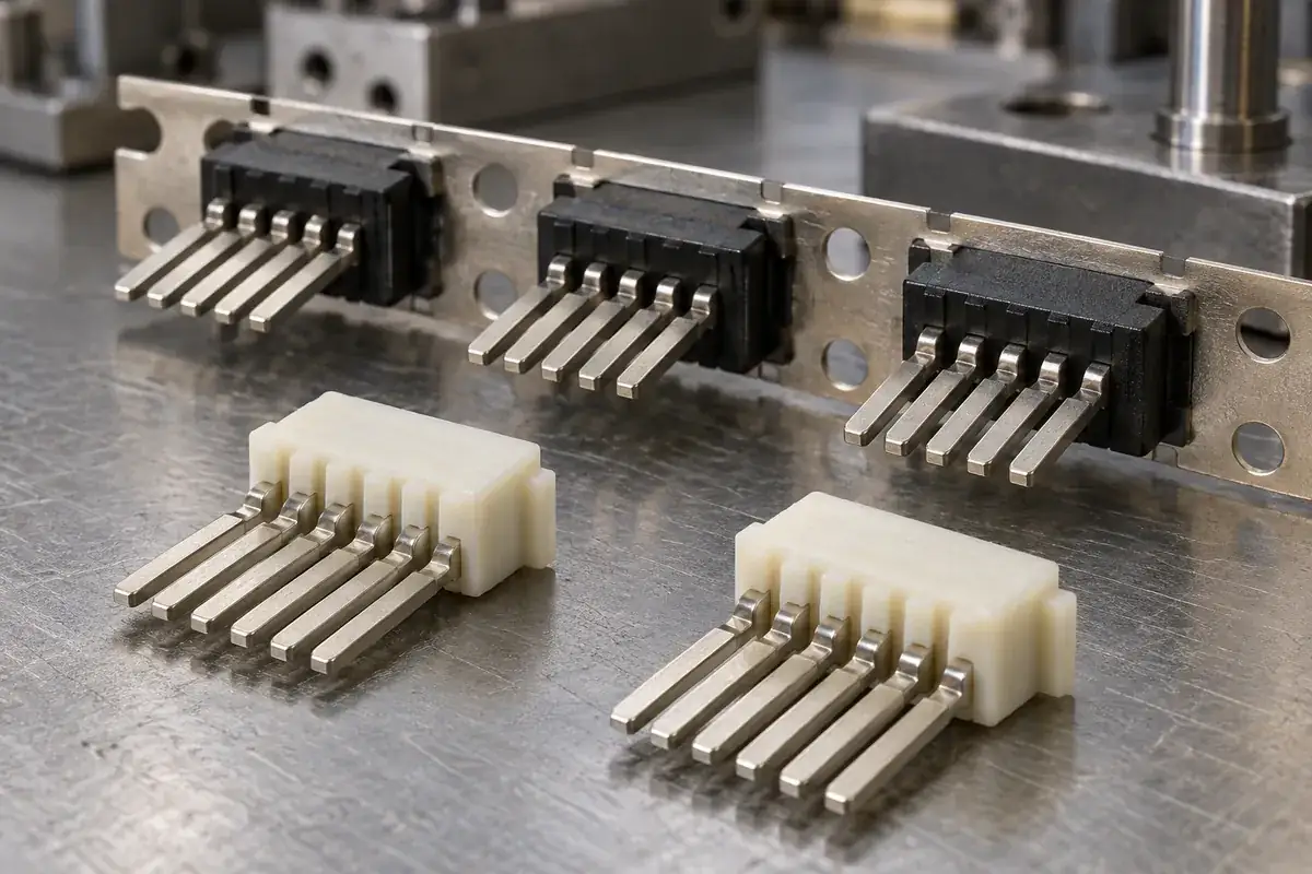
Product details
See the interfaces between the terminal and the molding
These product design illustrations show the contact array, captured terminal roots, carrier features and exposed metal surfaces that need to be defined for a connector insert-molding program.
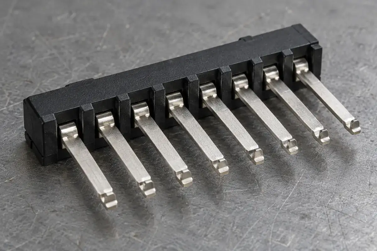
Contact array
Product design illustration: define contact pitch, tip position and the datum used to locate the array.
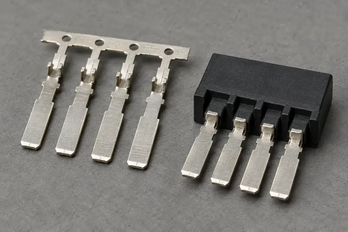
Molded retention region
Product design illustration: review the metal features captured by the plastic and the surrounding wall geometry.
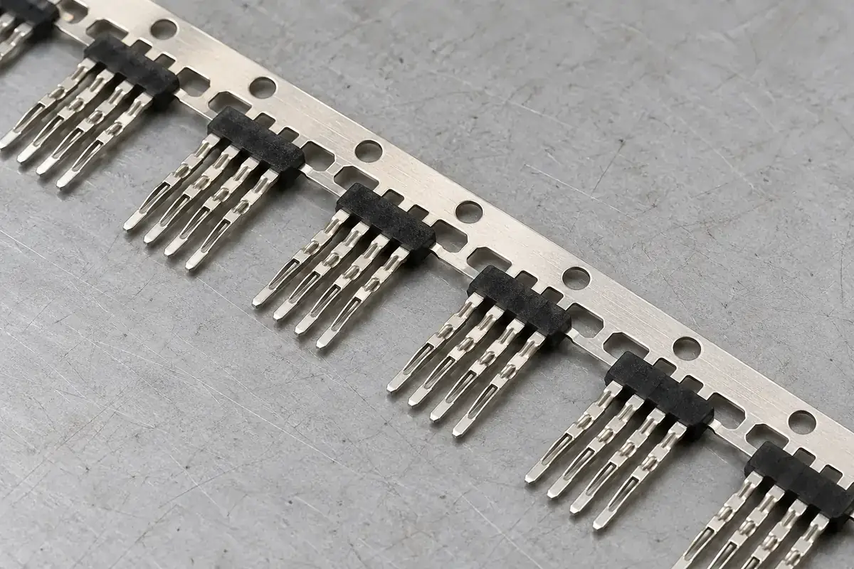
Carrier-strip references
Product design illustration: agree strip location, handling references and the bridges that remain until separation.
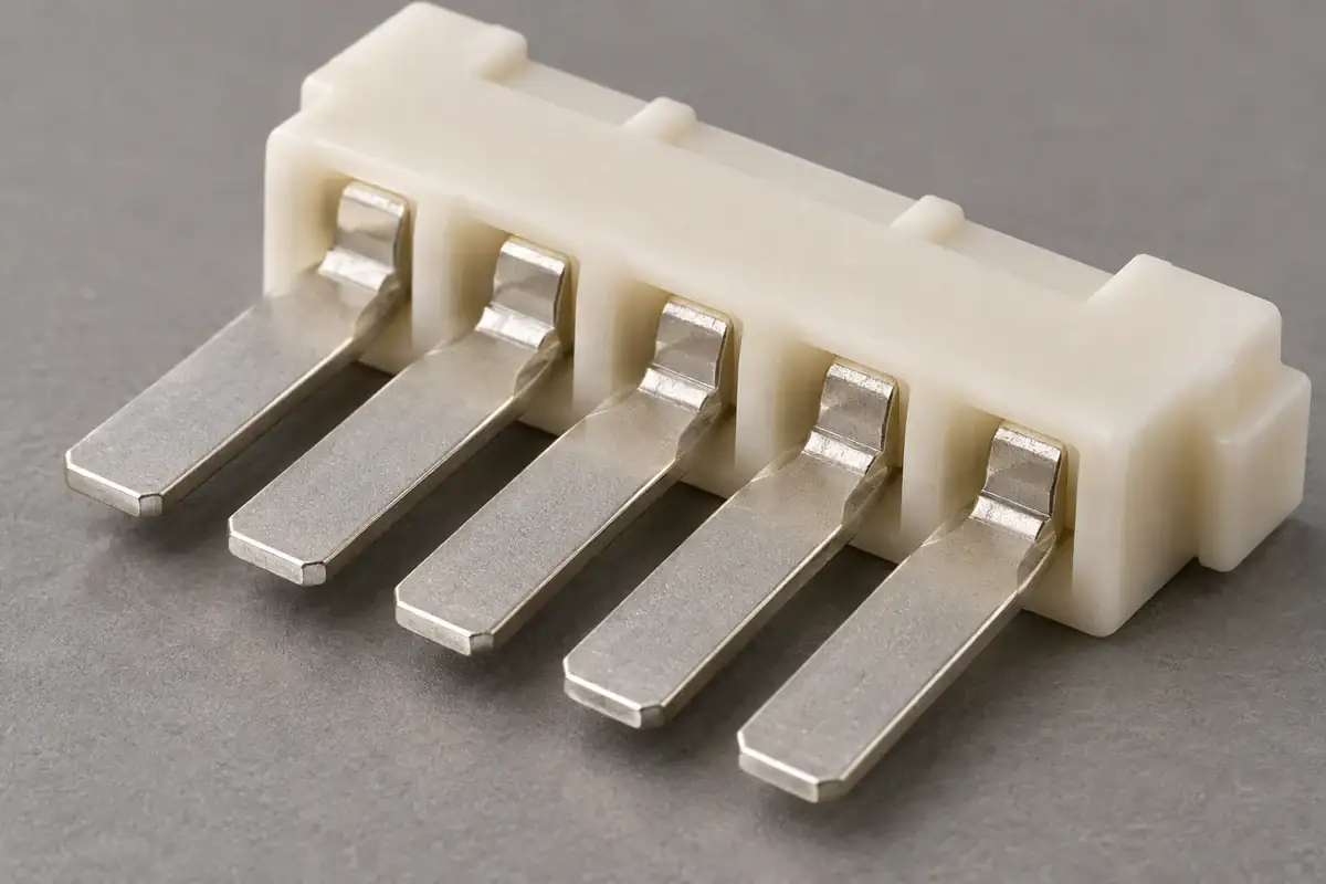
Exposed contact surfaces
Product design illustration: mark the contact and termination areas that must stay clear of resin and gate witnesses.
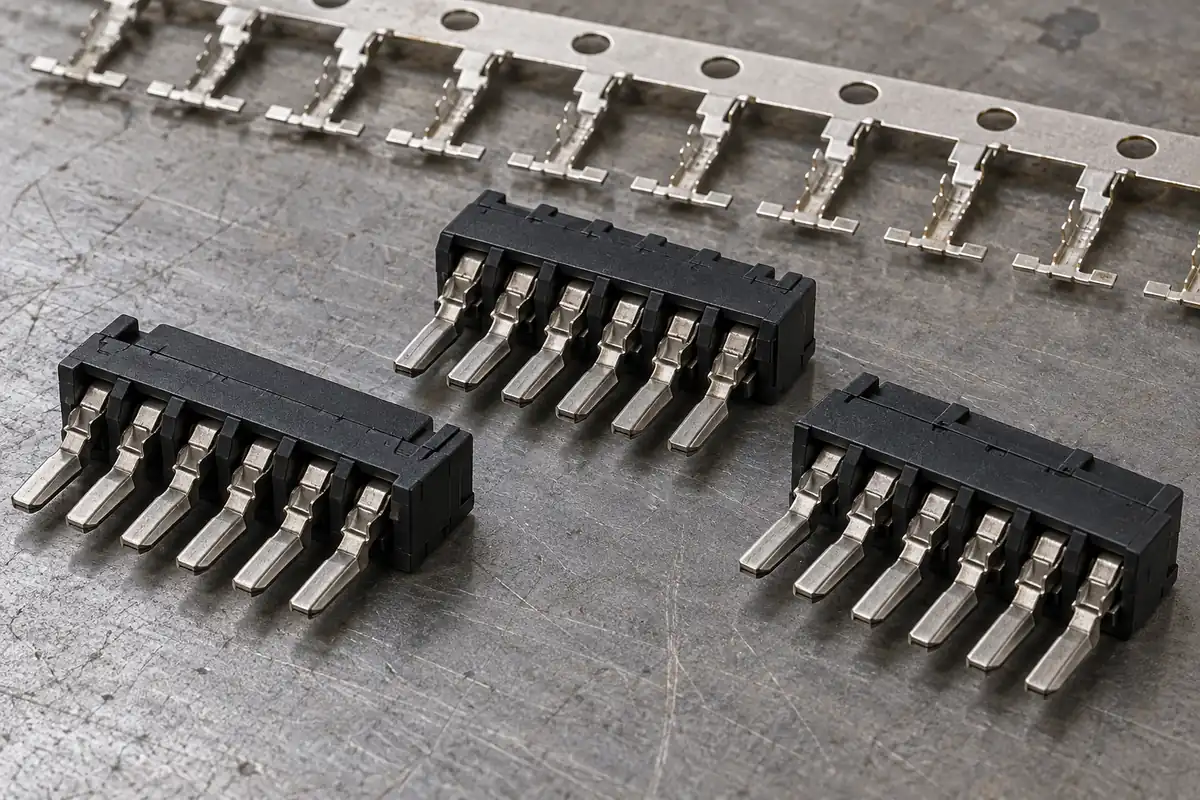
Separated component
Product design illustration: check terminal position and the specified cut condition after separation from the strip.
Illustrative configurations. Final specifications follow your approved drawings.
Application fit
Connector components built around their contacts
In this construction the contacts are present during molding. The plastic captures their defined retention regions while mating and termination surfaces remain exposed. That makes the incoming metal geometry part of the molding review from the start.
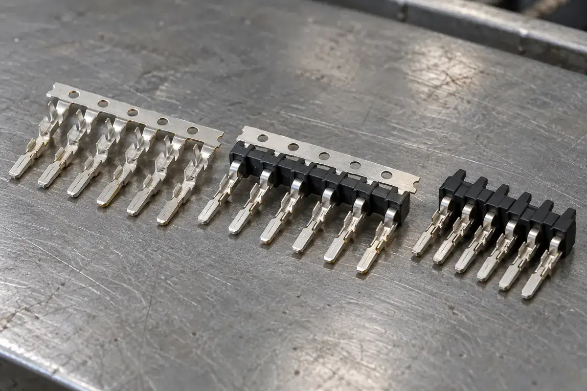
Molded contact-array modules
Plastic carriers with defined rows or patterns of metal contacts. Review where the mold supports the terminals, how the array is located and which contact surfaces the next assembly operation uses. The terminal pattern and the plastic locating features need a shared datum scheme.
Carrier-strip molded components
Terminal groups molded while supported by a stamped strip. Pilot features, tie bridges and the strip envelope influence loading, mold access and handling. Agree whether the delivered item remains attached to the carrier or is separated before shipment.
Separated terminal-and-plastic subcomponents
Individual components prepared for a customer-defined housing or downstream assembly. Review the cut locations, exposed metal edges, terminal position and packaging supports in the separated state, because removal of the carrier changes how the part is restrained.
Quote-ready inputs
What to send for a meaningful quotation
Use the same drawing and requirements for every proposal. Mark open decisions explicitly so that a low price does not conceal a different deliverable.
| Area | Please provide | Review before release |
|---|---|---|
| Terminal and strip definition | Terminal CAD and drawing, alloy and temper, thickness, plating requirements, burr direction and carrier layout. | Identify the surfaces used for mold location, retention, electrical contact and downstream termination. |
| Plastic geometry and resin | Component model, exact grade if selected, reinforcement, color and thermal or chemical exposure. | Review flow around the metal, wall transitions, shrinkage and the required condition after processing. |
| Location and shutoffs | Contact pitch, datums, permitted terminal movement and areas that must remain resin-free. | Develop the support and shutoff concept together with the allowable variation of the incoming terminals. |
| Separation and assembly | Required delivery state, carrier cut locations, forming sequence and mating assembly drawings. | Define the features checked after cutting or forming and protect the contacts during handling. |
| Inspection and approval | Critical features, sample quantity, cavity or strip-position traceability and required reports. | Agree dimensional methods and any retention or electrical checks separately, with clear test conditions. |
| Production and supply | Development quantity, recurring demand, packaging, supplied inserts and responsibility for each operation. | Prepare a quotation covering the approved terminal, tooling, molding and delivery configuration. |
From drawing to approval
Develop the terminal and mold as a connected process
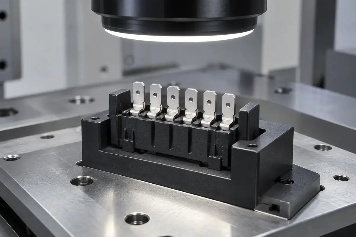
Reconcile the metal and plastic drawings
Start with the terminal geometry in its molding state and the required finished component. Resolve differences between strip, individual-contact and assembly drawings. Mark the protected contact surfaces and identify which dimensions belong to the stamped insert and which belong to the molded component.
Plan location, flow and release
Review how the strip or separate terminals are supported while the mold closes and fills. Develop gate, vent and shutoff locations around those supports. Include incoming metal variation, plating condition and the route for removing the part from the tool in the feasibility review.
Trial the complete sequence
Inspect identified inserts before molding and the resulting components afterward. Evaluate relevant contact positions, resin coverage and exposed surfaces. If the carrier is removed, repeat the agreed geometry checks after separation rather than releasing the part from on-strip measurements alone.
Release the manufacturing configuration
Record the accepted terminal and resin specifications, drawings, tooling configuration, separation method and inspection plan. Define packaging around the exposed contacts. Changes to terminal stock, plating, resin or tooling are then reviewed against that approved configuration.
Practical engineering and buying guides
Decisions to make before production
- Connector Insert Molding vs Contact AssemblyCompare molding plastic around connector terminals with installing contacts afterward. Understand location, retention, tooling and assembly trade-offs.
- LCP, PBT or PA9T for Connector Insert Molding?Evaluate LCP, PBT and PA9T connector materials by exact grade, wall geometry, flow direction, moisture history and the intended assembly environment.
- Locating and Supporting Connector Leadframe CarriersUnderstand how carrier references, strip support and terminal restraint work together during connector insert molding and after carrier removal.
- Connector Terminal Shutoffs and Flash ControlExplore how terminal variation, tool support and molding conditions affect flash at connector interfaces, especially around exposed mating contacts.
- Thin-Wall Connector Molding: Filling, Welds and VentingFollow polymer flow around connector terminals to understand thin-wall filling, weld-line placement, air escape and the limits of process adjustments.
- Connector Terminal Shift During Insert MoldingUnderstand how melt loading, unsupported terminal spans and tool support affect connector terminal position, and how to isolate the cause of movement.
- Protecting Plated Contacts During Connector Insert MoldingPlan contact-zone protection, carrier handling and inspection so plated connector terminals survive loading, molding and transfer without avoidable damage.
- Why Connector Geometry Can Change After Carrier CutoffInvestigate connector movement after carrier cutoff by separating released restraint, trimming loads and measurement support from molding distortion.
- Connector Insert Retention vs Mating ForceSeparate terminal retention from connector mating force with clear load paths, fixtures and acceptance conditions for insert-molded connector components.
- Connector Insert Molding: Prototype to Production ToolingMove connector insert molding from samples to production by reviewing terminal support, feeding, cavity balance and release conditions before tool transfer.
Related connector manufacturing scopes
Explore empty insulating bodies, components molded around metal terminals and the precision mold inserts used to form them. Each scope has its own drawings and acceptance requirements.
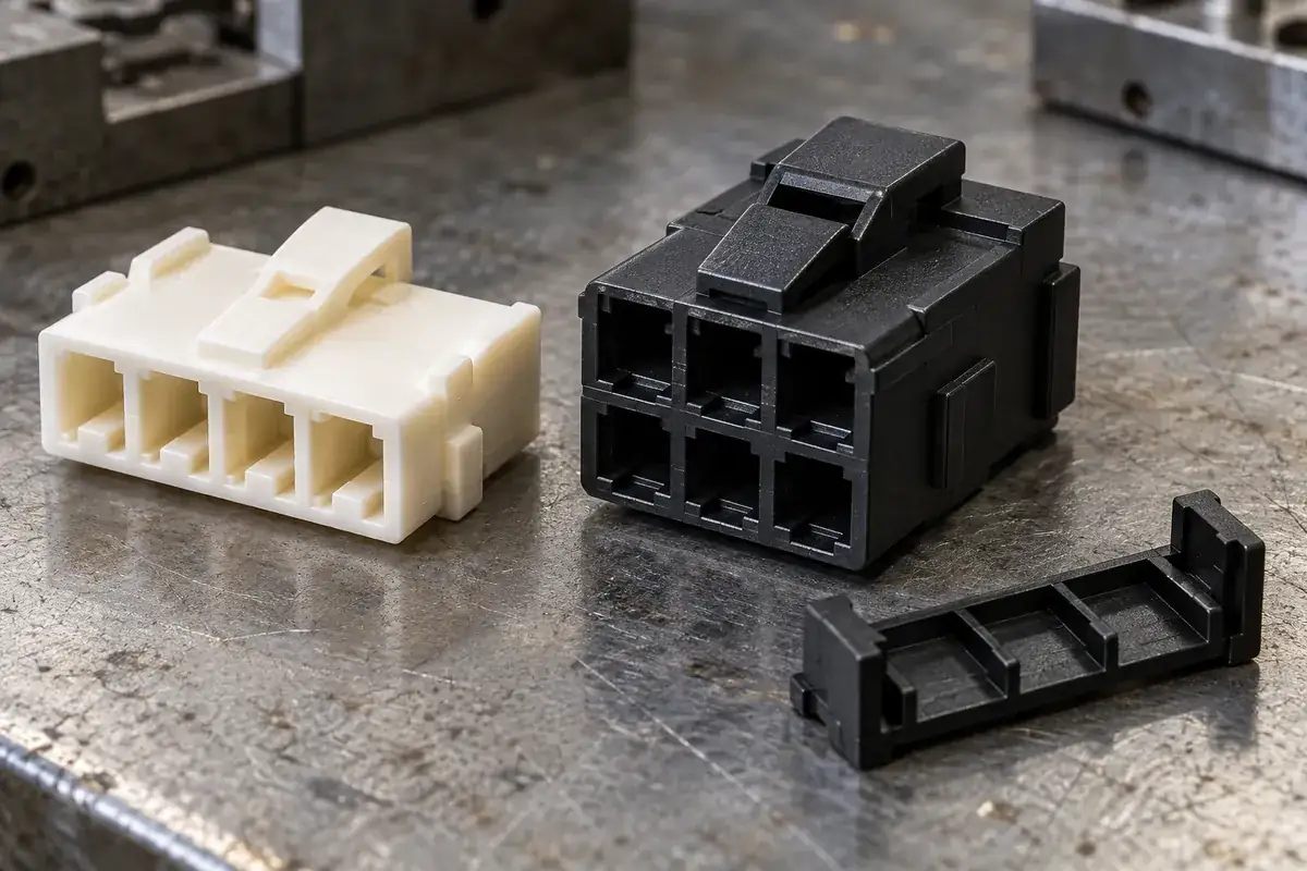
Custom Wire-to-Board Connector Housings
Custom injection-molded wire-to-board connector housings. Review crimp-terminal fit, wire entry, latches, keying and tooling for your plastic components.
Review the application →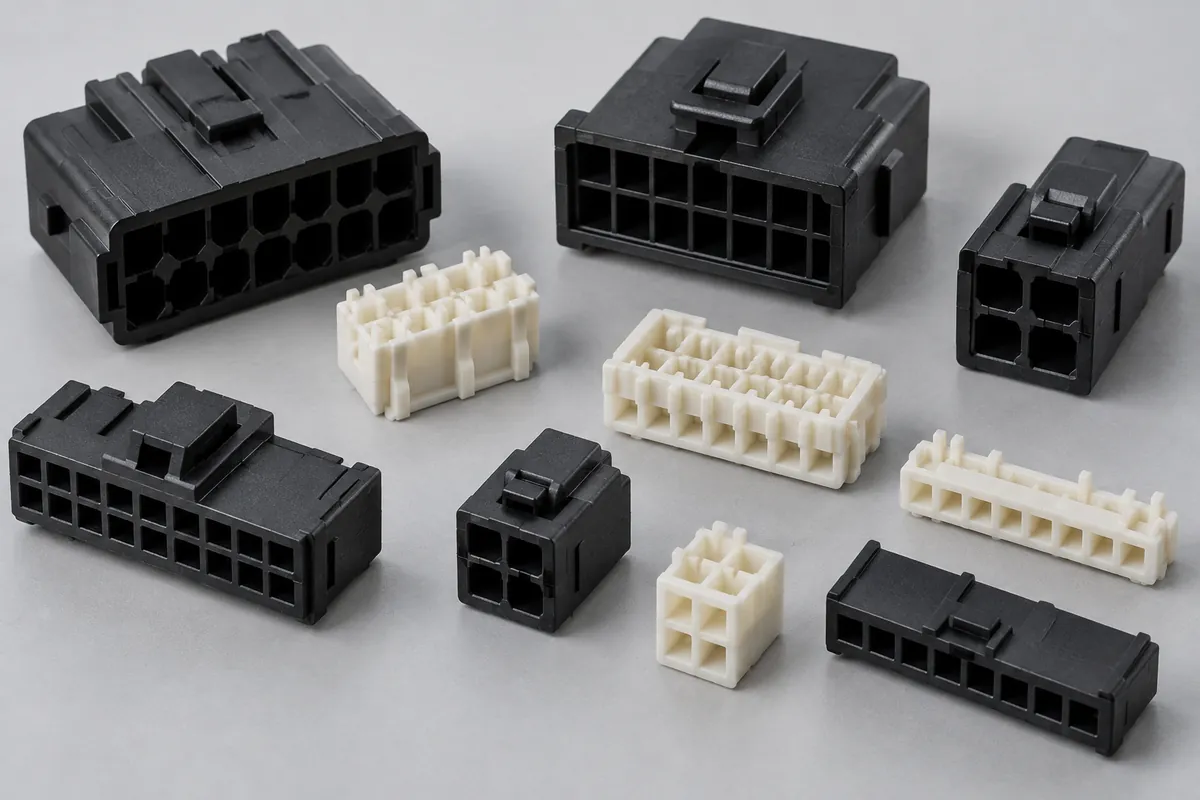
Connector Insulators & Terminal Carriers
Custom molded insulating bodies and terminal carriers. Define terminal interfaces, locating references, exact resin and component acceptance.
Review the application →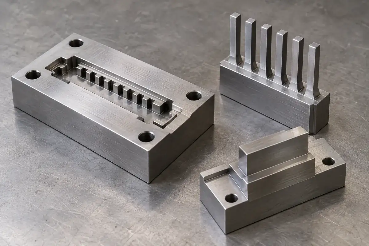
Precision Connector Mold Inserts
Custom steel mold inserts for connector tooling: cavity inserts, thin cores and comb features. Review drawings, locating fits, finishing and replacement scope with FECISION.
Review the application →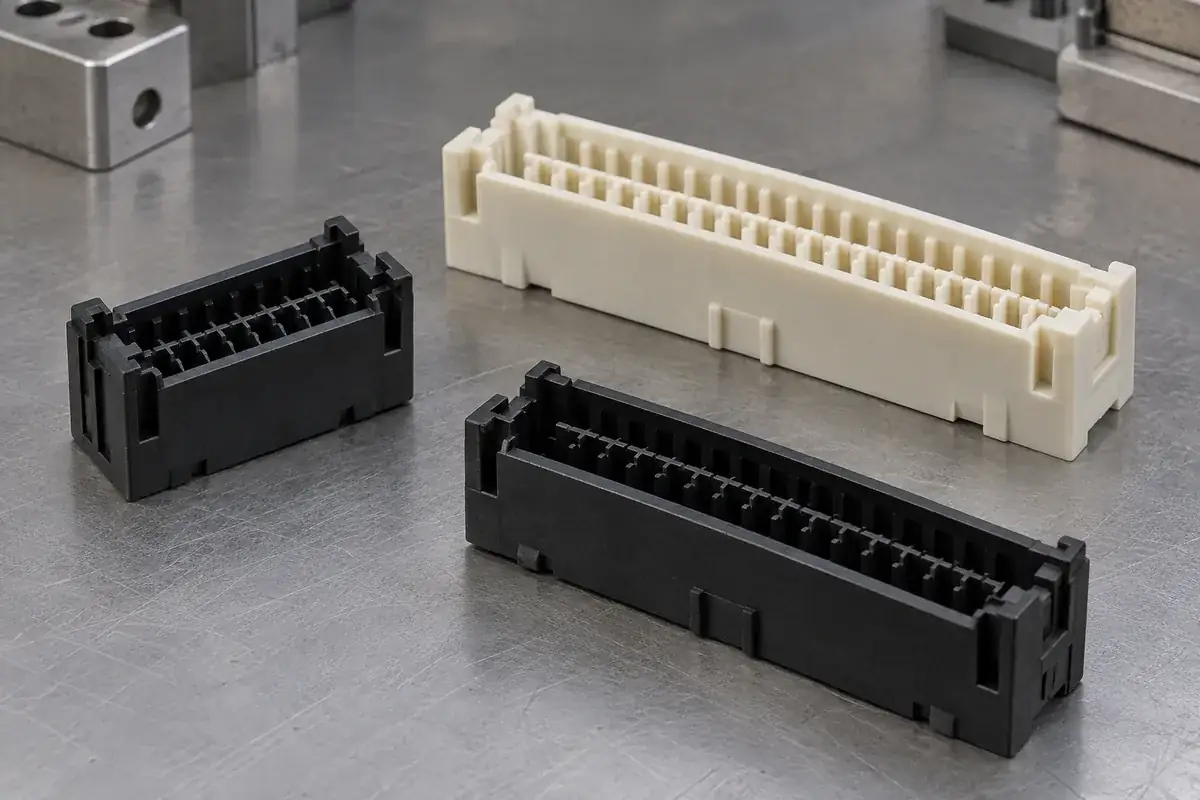
Custom Board-to-Board Connector Housings
Custom molded board-to-board connector housings. Review stack height, alignment, contact cavities, mounting features and inspection with FECISION.
Review the application →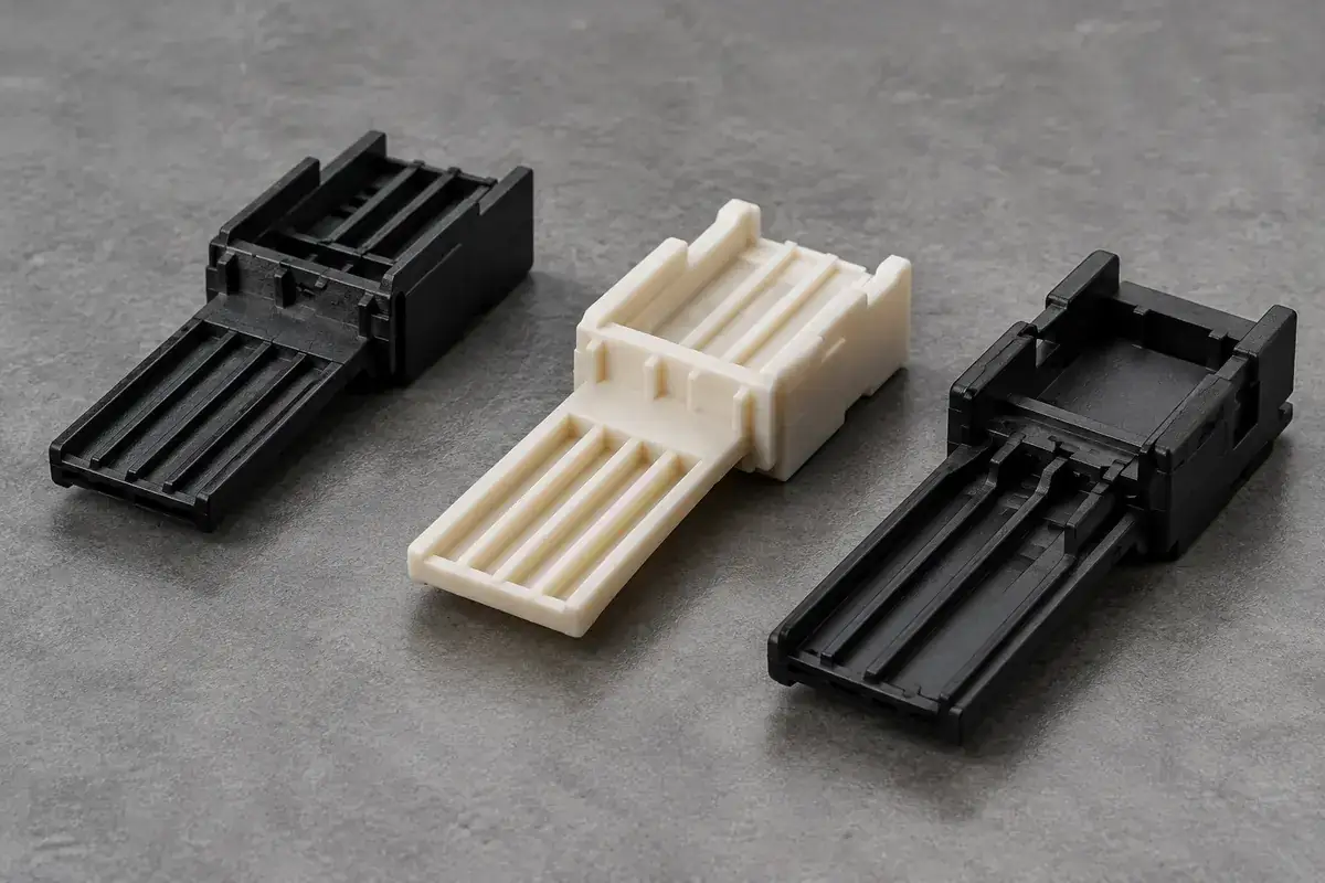
Custom USB Connector Insulators and Terminal Carriers
Custom molded USB connector insulators, tongues and terminal carriers. Review contact channels, shell interfaces, resin, tooling and inspection with FECISION.
Review the application →Before you request a quote
How is this different from molding an empty connector housing?
Here the metal terminals are located inside the mold before plastic is injected around their retention regions. An empty housing is molded first and receives contacts in a later assembly operation. The two routes have different tooling, terminal and inspection requirements.
Can stamping and insert molding be reviewed together?
Yes. Provide the terminal and strip drawings with the molded component definition. The quotation can define the stamping, plating, tooling, molding and separation responsibilities together, including any inserts supplied by you.
Can parts be delivered on a carrier strip?
On-strip and separated delivery can both be considered during feasibility review. Define the format required by the next operation, the strip references and allowable handling. For separated parts, agree the cut condition and the inspection performed after the carrier is removed.
Which plastic should the connector component use?
Select an exact grade against the geometry, molding route and actual service or assembly exposure. LCP, PPS, PBT and polyamide grades may be candidates for different requirements. A resin-family name alone does not establish a reflow profile or a finished connector rating.
What contact-position tolerance can you achieve?
Provide the critical positions, datums and measurement state. Incoming terminal variation, insert support, plastic shrinkage and separation can all affect the result. Feasibility and acceptance are reviewed for those features; toolroom equipment specifications are not finished-part tolerance commitments.
Does the component come with a current rating or connector certification?
Those belong to the defined connector configuration and its qualification. Specify the applicable electrical, thermal and mechanical requirements so component checks and completed-assembly tests can be assigned appropriately. A dimensional report or material certificate does not replace that qualification.
Your next step
Discuss the part with its intended function.
Send the terminal drawing, carrier layout and molded component model together. We will review how the contacts are located, which surfaces remain exposed and what must be checked before quoting your connector-component program.
Explore our connector injection molding service or review other connector components and mold inserts.