
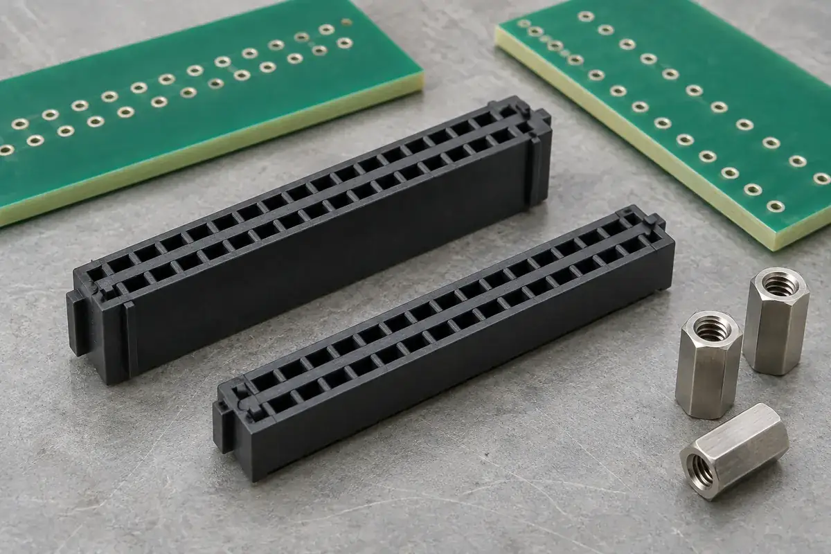
A board assembly can have the correct enclosure height and still squeeze its mezzanine connector. The enclosure drawing usually controls where the boards finish, while the connector drawing controls where the mating halves should finish. Those two statements become compatible only after the mounting faces, seating conditions and engagement travel have been connected.
For a custom molded housing, its overall plastic height is only one contributor. A taller guide wall may improve early alignment without changing the final board separation. A lower seating foot may change board separation even though the top of the housing remains unchanged. The useful dimension is therefore a functional relationship, not the largest number in the side view.
Product design illustrations accompany the engineering explanations below.
Start at the surfaces that support each board
Draw a section through the actual assembly and identify the two board surfaces used as references. A component-side spacing and an outside-face spacing are different quantities because board thickness lies between them. Record which one the mechanical design controls before adding the housing dimensions. Otherwise, a thickness allowance can be included twice or omitted entirely.
Next locate the housing seating surface on each board. Feet, shoulders, soldered attachments or a separate carrier may establish that location. The nominal underside of a plastic model is not necessarily the surface that touches the board. Local relief, molded projections and the assembly process can all create a different effective seating condition.
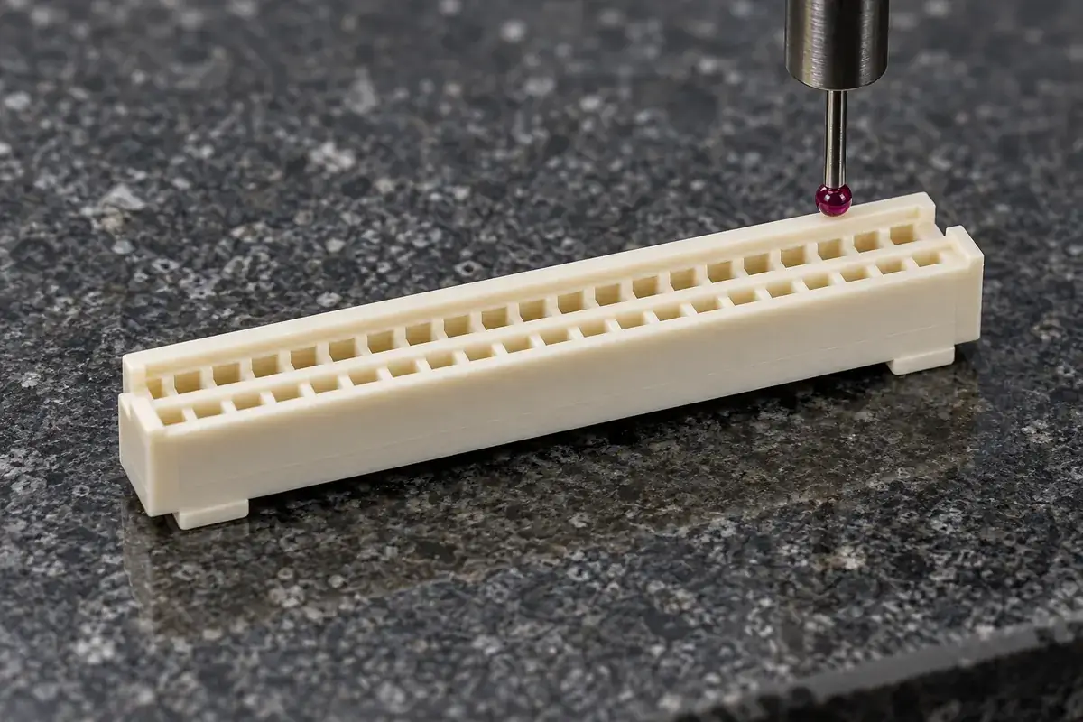
Use one consistent direction for the stack calculation. Moving from the lower board through its housing to the mating reference and back through the upper housing should arrive at the specified upper-board plane. This simple closed path exposes missing offsets. It also makes sign errors visible when a dimension increases engagement while another increases the gap.
The contact system adds another boundary. A molded wall may reach its final position before or after the contacts reach their intended operating engagement. The contact designer must define the permitted relationship. A housing supplier can reproduce agreed plastic geometry, but cannot infer contact wipe, spring deflection or electrical reliability from a plausible-looking section.
Separate the engagement window from the nominal height
A nominal mated height describes the intended assembled position. It does not explain how far the connector can remain short of that position or move beyond it. Treat minimum engagement, intended seating and maximum permitted travel as separate conditions. Their distances may be small, yet they answer different questions during assembly and tolerance review.
At the largest board separation, verify that the contact and guide relationships still satisfy the approved assembly definition. At the smallest separation, check that shoulders, housing roofs or other solid features do not receive unintended compression. The relevant extremes come from the complete stack, including the mechanical supports that force the boards into position.
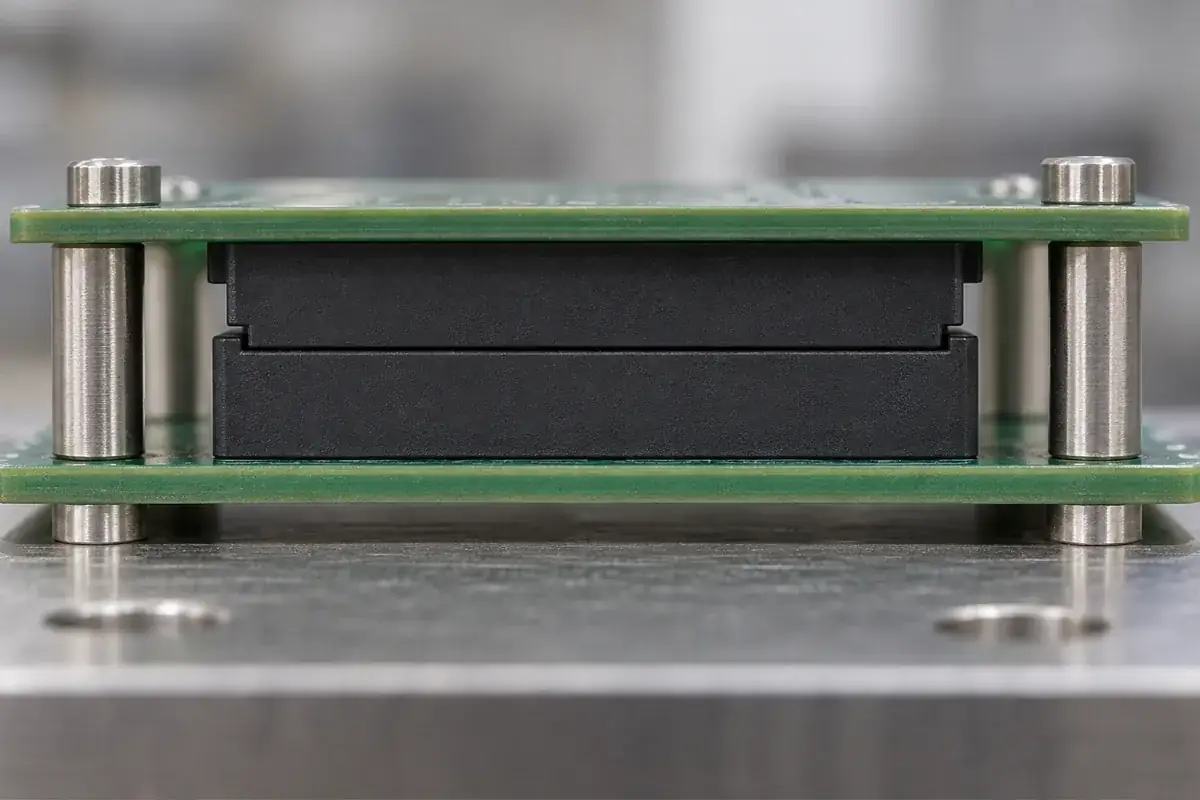
Imagine a board pair located by four metal standoffs. If their assembled separation is shorter than the connector's intended position, tightening the fasteners can keep moving the boards after the connector has seated. The plastic may then appear to be the source of a height problem even though the controlling dimension belongs to the support structure.
Conversely, generous standoff height can leave the assembly visually closed while the connector remains only partly engaged. A cosmetic enclosure gap is a poor substitute for engagement evidence. Determine which interface stops movement and which observable feature confirms completion. The separate guide to assembly overtravel examines what happens after the intended engagement point.
Variation has both a direction and a physical source
Housing height variation can come from local geometry, material response and the condition in which the part is measured. Board thickness, mounting hardware and assembly placement have their own contributors. Keep these sources separate in the stack so a drawing change addresses the correct mechanism. Tightening an unrelated housing dimension may add cost without protecting the critical gap.
A worst-case stack asks whether the permitted extremes can coexist without violating the functional limits. A statistical model asks a different question and depends on justified distributions, centering and independence. A symmetrical tolerance on a drawing does not prove a normal process distribution. Select the method with the product team rather than silently replacing a guaranteed envelope with a probability estimate.
Board bending complicates a calculation made from rigid dimensions. A board may satisfy its free-state requirement yet change shape when fastened to an uneven support system. If the connector sits away from the supports, the local separation can differ from the spacing measured at the screws. Evaluate the connector location, especially when the board pair is large or thin.
Hirose's DF40 catalog calls for additional board support rather than relying on the connector alone. That product-specific guidance illustrates why housing height and structural board support should be reviewed together; its dimensions are not specifications for a custom housing.
Choose the adjustable feature deliberately
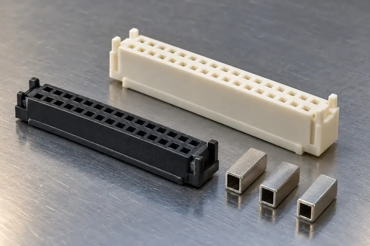
During development, it is useful to know which dimension can be tuned without disturbing every other interface. Changing a seating foot can alter the board-to-housing position. Changing a mating shoulder can alter engagement. Changing a guide-wall height may mainly change when alignment begins. These edits are not interchangeable even when each removes the same amount of plastic.
Review tool construction before assigning an adjustment range. A replaceable detail may provide a controlled development route, but a geometrically convenient change can still affect filling, ejection or a neighboring feature. The broader connector insulator review is useful for resin and cavity considerations; the stack-height decision must remain tied to the board assembly.
Inspection should reproduce the reference state in the calculation. Specify whether the housing rests freely, seats against a fixture or is installed on a representative board. A measurement under force can conceal an interference that appears during assembly. Equally, a free-state height can exaggerate a harmless deflection that the approved mounting method is intended to control.
For custom board-to-board connector housings, provide the housing section, counterpart and support geometry as one review set. Identify the intended mating position and the permitted extremes. That allows plastic dimensions to be assigned to a defined engagement window instead of treating overall height as a guarantee for the complete connector.