
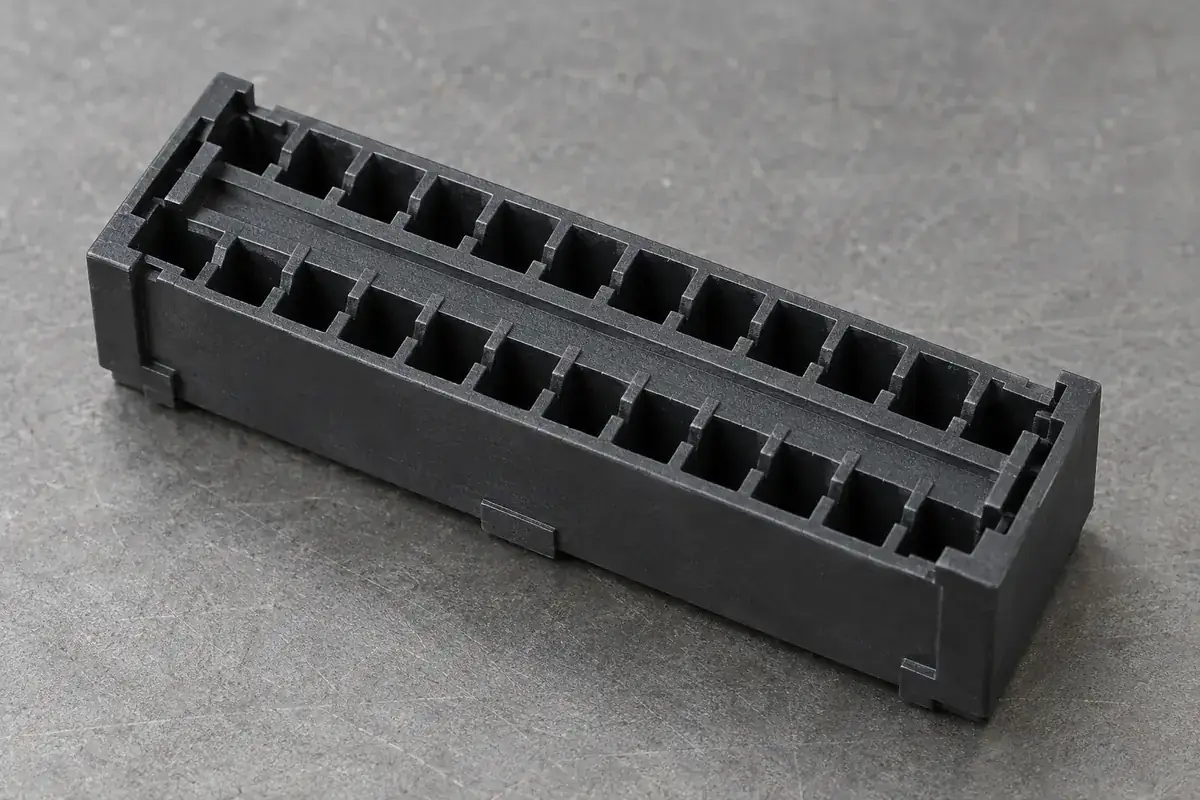
An empty connector cavity has several jobs before it ever carries an electrical contact. It must admit the contact in the intended direction, guide it without damaging sensitive regions, allow the retention feature to engage and stop the contact at the correct position. A cavity that looks dimensionally plausible can succeed at one job while failing at another.
Retention should therefore be reviewed as an assembly sequence and a load path. The plastic and the contact form a pair, even when they come from different suppliers. A housing drawing alone rarely explains which contact surface deflects, which shoulder carries pullout load or how an operator confirms that insertion is complete.
Product design illustrations accompany the engineering explanations below.
Identify the feature that actually retains the contact
Some contacts use a resilient metal feature that engages a molded shoulder. Other designs use interference, a separate retainer or a different approved mechanism. These arrangements place different demands on the cavity. Do not transfer a familiar retention detail into a new housing without the contact definition and its intended installation method.
In a shoulder-and-lance arrangement, distinguish the lead-in surface, the clearance needed during deflection and the final retaining face. The ramp helps installation, while the retaining face resists withdrawal. Blending both into one smooth feature may reduce insertion resistance yet weaken the mechanism that prevents the contact from backing out.
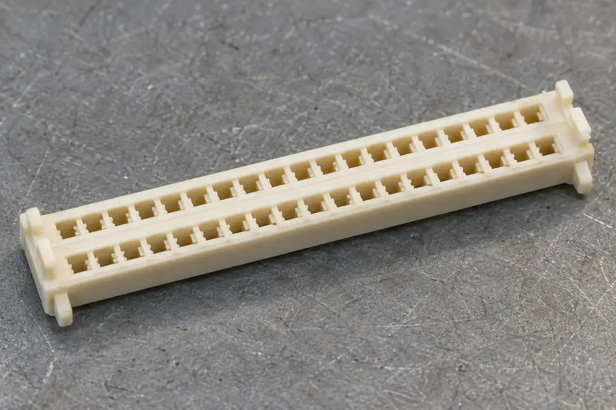
A retention load travels from the contact through a local plastic feature into the surrounding body. The root section and nearby walls matter as much as the apparent overlap. A shoulder attached to a slender unsupported divider can bend under load even when its nominal engagement looks generous. Follow the load into the full housing, not just across the contacting surfaces.
The contact's allowable insertion and withdrawal behavior belongs to its approved design and assembly requirements. A plastic supplier should not assign a universal force from cavity dimensions. Material condition, contact tolerances, surface treatment and assembly direction all affect the result. Agree which component checks and which populated-assembly evaluations establish acceptance.
Make room for installation without losing the final position
The cavity must provide a path for the contact's largest relevant envelope during insertion. That envelope can differ from the final seated cross-section because a spring feature deflects or a formed section passes through the entrance. Reviewing only the final CAD position can hide an interference that occurs halfway through the motion.
Excessive clearance is not a universal remedy. It may allow the contact to tilt, enter the wrong guide region or approach the retaining shoulder obliquely. A long unsupported contact can then transmit insertion force through a corner rather than its intended surface. The cavity should guide the appropriate contact regions while leaving the necessary deflection space.
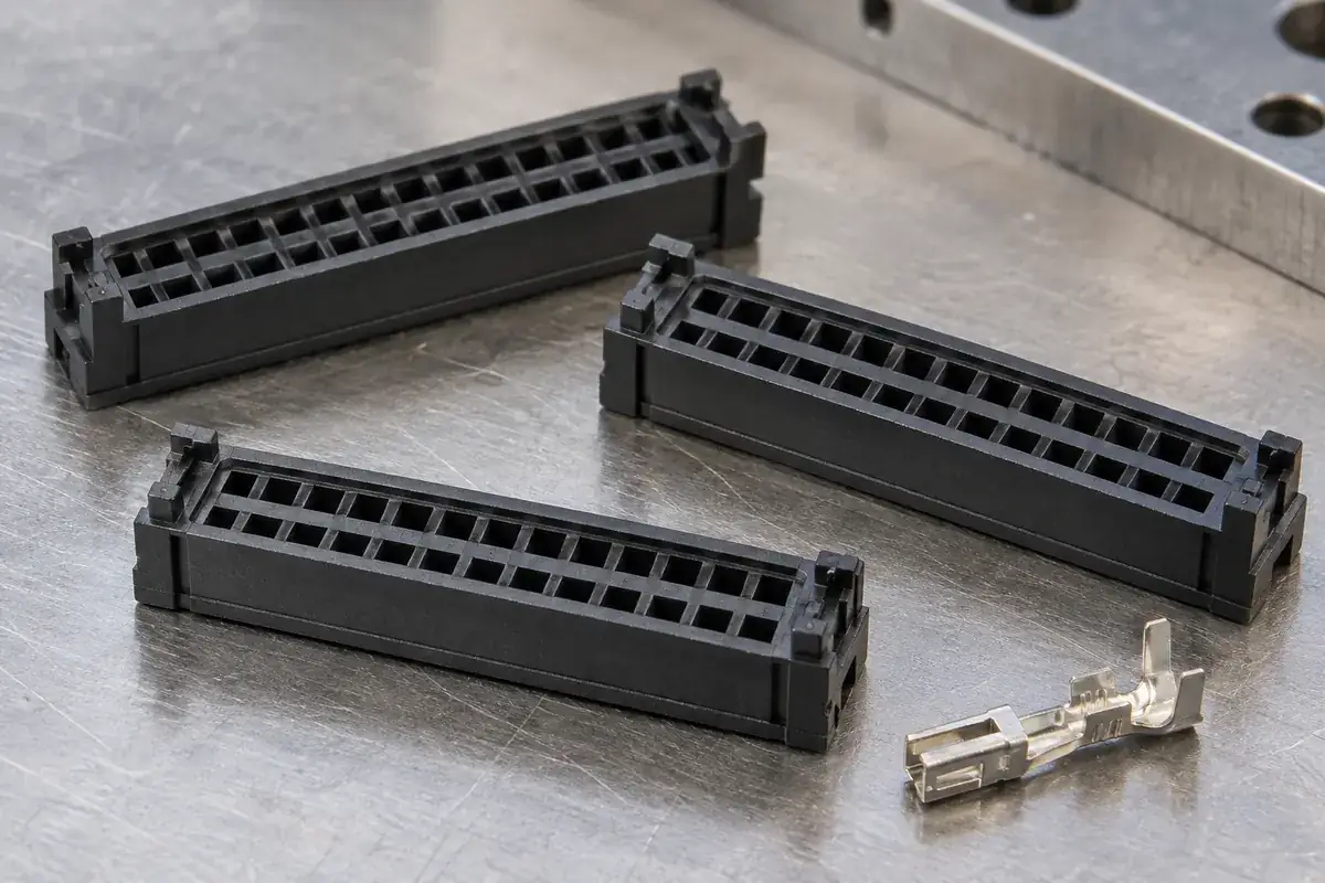
The final stop and the retention shoulder also need a compatible axial relationship. If the stop arrests motion too early, the retention feature may never engage. If the stop lies too far away, the contact may travel beyond its intended location before retention occurs. Both extremes should be evaluated with the approved contact geometry.
Confirmation of seating deserves its own feature or process. An audible click may be absent, inconsistent or inaccessible in an automated station. A visual window, a controlled position check or an agreed functional method may be more suitable. Choose the confirmation around the actual assembly rather than relying on the sensation obtained from one loose prototype.
Protect the cavity from manufacturing conflicts
Small internal shoulders may require a tooling split, local core detail or another release strategy. That construction influences where a parting line, mismatch or flash could occur. Identify the contact's travel and bearing surfaces early so the tooling proposal does not place an uncontrolled witness directly in the retention interface.
Draft affects the available width through a cavity. A contact may enter a generous mouth and bind near the intended seat if the controlling section is not specified. Conversely, an inspection made only at the narrowest section may miss a large entrance that permits tilting. The correct measurement locations follow the assembly functions along the cavity.
A local gate or flow transition can affect thin internal features differently from the outer shell. That does not justify predicting a defect from geometry alone, but it does justify reviewing how those features fill, cool and release. Early sample inspection should include the retaining shoulder and its relationship to the entry path, not only the external envelope.
Hirose's DF40 handling cautions describe contact damage from inappropriate mating or unmating. They reinforce a limited but useful boundary: preserving plastic geometry is only part of protecting the contact system, whose handling requirements remain assembly-specific.
Use component evidence and assembly evidence together
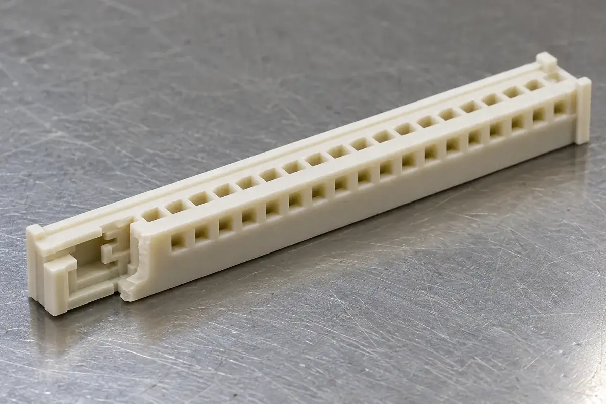
Dimensional inspection can establish the cavity profile, shoulder position and relevant wall condition. It does not directly measure the retention behavior of an unknown contact. A populated-assembly evaluation can assess that behavior, but its result depends on the terminal revision, installation method and specimen state. Keep these evidence sets connected without treating them as interchangeable.
For a multi-cavity mold, relate each sample to its source cavity. A retention issue concentrated in one population may indicate a local geometry or process difference. Combining all samples into one average can conceal it. The cavity inspection plan explains how functional features and production identity can remain traceable.
Also review service and rework. A contact designed for one-time insertion may not tolerate repeated removal, while a releasable mechanism needs access and a defined tool path. Increasing retention to address an assembly issue can make authorized rework impossible. The intended lifecycle should be part of the design decision before tooling is committed.
Our insert molding versus contact assembly guide addresses the manufacturing sequence choice. For custom board-to-board housings assembled with contacts afterward, the immediate requirement is a controlled pair: contact, cavity, insertion method and acceptance evidence. Empty molded-part supply alone does not establish a complete connector's electrical rating or retention performance.