
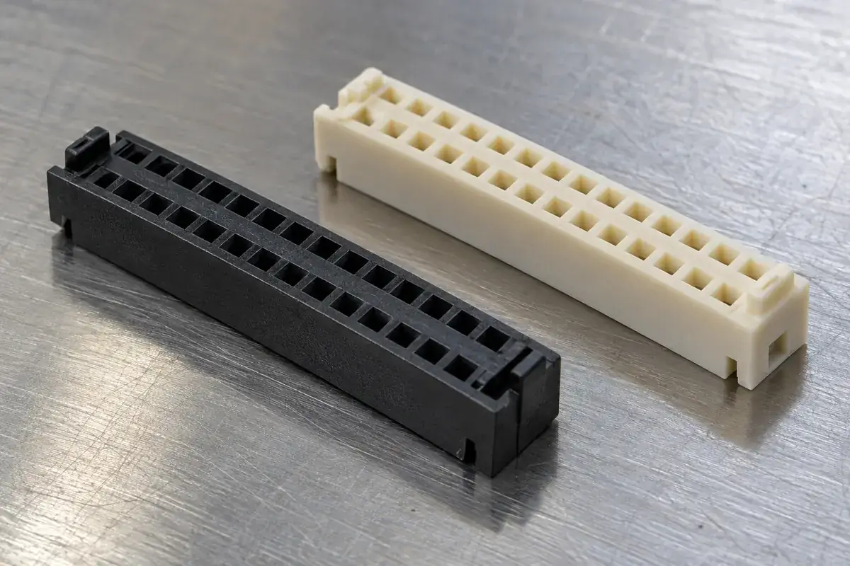
A polarization key should make the wrong assembly physically unavailable at the right moment. An asymmetric feature that becomes effective only after the contacts have entered may identify orientation on a drawing yet offer little protection during actual mating. The important question is when the key meets its counterpart relative to every vulnerable feature.
For board-to-board housings, the boards and their surrounding hardware can obscure the mating face. Assembly may occur from an angle that makes a small molded detail difficult to see. A useful key therefore needs to work mechanically as well as visually. Color, arrows and operator familiarity can support the process, but they do not establish the physical rejection sequence.
Product design illustrations accompany the engineering explanations below.
Distinguish orientation from variant coding
Polarization prevents a given pair from mating in an incorrect orientation, such as a half-turn reversal. Coding prevents two similar but intentionally incompatible variants from mating. They are related design tasks with different coverage. One offset rib may polarize a housing while still allowing it to enter every other product variant in the same equipment family.
List the incorrect combinations that the design must reject. Include reversed parts, similar circuit counts where relevant, adjacent sockets and replacement variants. Do not assume that a feature effective against one reversal covers every misuse. This comparison is especially important when several housings share the same outside envelope or a common molding platform.
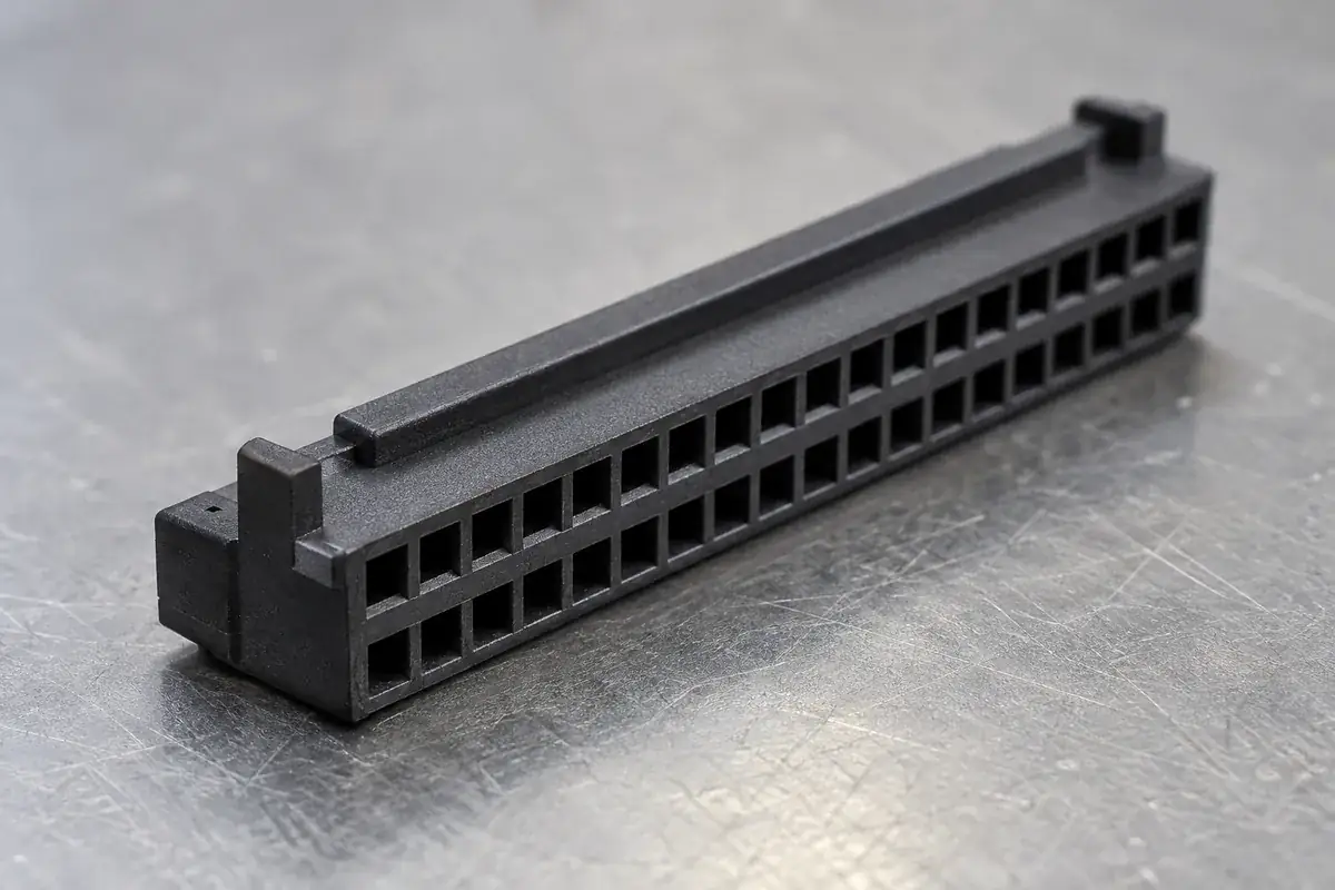
A matching key and slot must preserve an orientation signal after all allowed symmetries are considered. Two identical keys placed symmetrically can look more secure while restoring the very reversal that one offset key prevented. Evaluate the complete pair in each possible orientation, including the shape of the surrounding wall rather than only the added rib.
Molex's SlimStack floating-series datasheet identifies polarization as a feature for preventing mismating. A custom housing still needs its own wrong-orientation geometry review; the presence of a key does not transfer the performance of a catalog connector to a different design.
Make rejection occur before damage becomes possible
In a correct approach, the key should enter without forcing the board away from the alignment established by other guides. In an incorrect approach, a robust stop should meet before delicate contact or cavity features overlap dangerously. These are two different engagement sequences. Inspect both through the full approach travel, not just at the final mated position.
Consider the extremes of key height, receiving-slot depth and housing position. A key that rejects a nominal reversed model might arrive late when it is shortest and its counterpart is farthest away. Equally, an overly long key can bottom in the correct orientation before the connector reaches its intended seating position. Stack these relationships explicitly.
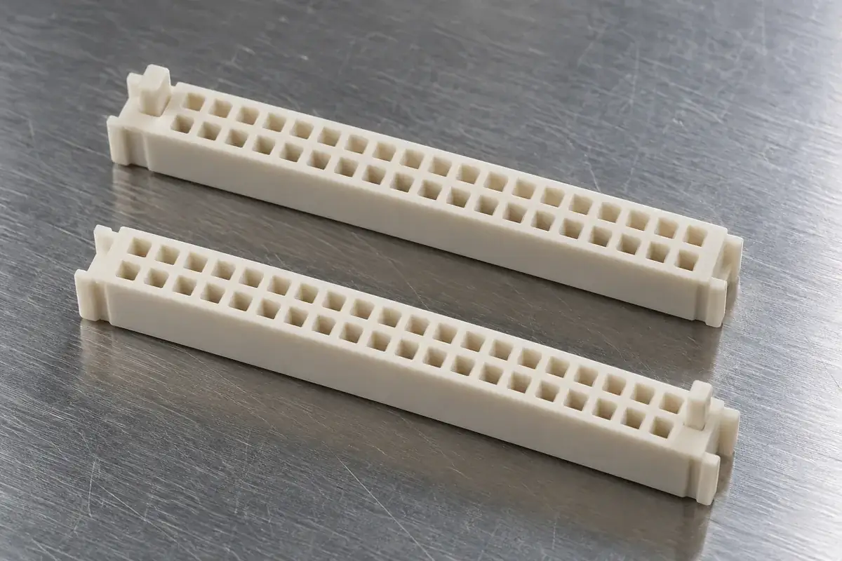
The force path during rejection deserves attention. A tall thin rib can bend, shear or ride over a chamfer when a board is pressed obliquely. A wider, well-supported blocking surface may distribute load better but needs more space and mold access. The design objective is controlled rejection under the agreed assembly conditions, not simply adding the largest possible obstruction.
Do not use the delicate wall between contact cavities as the primary misuse stop if a more suitable structural region is available. Concentrating an assembly error there can damage an internal feature before the outside housing shows obvious distress. The contact-cavity retention discussion explains why those small features already carry a separate assembly responsibility.
Balance key clearance with guidance
A key can also guide, but combining the roles can create competing requirements. A generous slot clearance makes correct insertion easier and preserves room for the main guides to align. A tight slot may improve angular control, yet it adds another precise locating interface. Decide whether the key is a rejection device, a guide or a deliberately combined feature.
When several guides locate the same housing, a tightly fitted key can overconstrain the assembly. The part may enter each feature individually but fail when they engage together. Review key position relative to the primary datums and counterpart, then allocate clearance accordingly. The multi-connector alignment guide describes the same conflict at board scale.
A lead-in on the correct side can help the key enter its slot. On the blocking side, excessive rounding may allow an incorrect pair to climb past the intended stop. Edge conditions therefore belong to the functional definition. A general instruction to break every edge may unintentionally weaken the rejection geometry if the critical surfaces are not identified.
Mold release also affects the key profile. Draft changes the width along its height, and a root radius changes how the rib joins the wall. These are useful manufacturing features when included in the approved geometry. They should not appear later as undocumented adjustments that reduce blocking overlap or create interference at the bottom of the correct slot.
Keep identification and physical compatibility connected
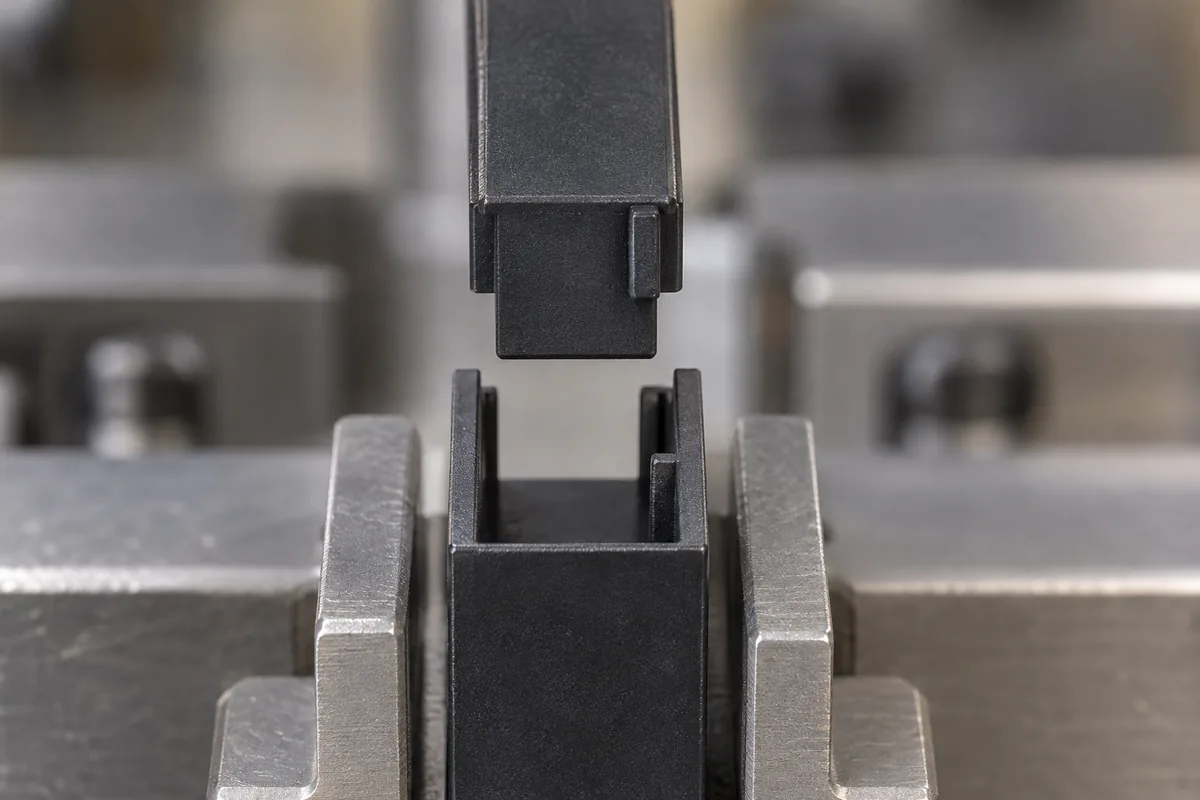
For a family of coded variants, the production identity should follow the physical key configuration. Interchangeable mold details can make variants economical, but they also create a changeover responsibility. Part identification, tool configuration and packing need to distinguish the approved versions. A correct drawing is insufficient if two physically different variants are mixed after molding.
Visual inspection can confirm that a key exists and appears in the intended location. It does not prove rejection of every wrong counterpart. Use representative mating masters or other agreed checks for the combinations that matter. Preserve the distinction between verifying geometry and demonstrating the behavior of a complete populated connector under load.
Development evaluation should include a correct pair at challenging alignment conditions as well as the defined incorrect pairs. A key that prevents every assembly, including the intended one, has not solved the problem. Record the approach direction and stopping condition so improvements in misuse rejection do not quietly make the normal assembly process unreliable.
For custom board-to-board connector housings, share the counterpart and variant matrix with the plastic drawing. The broader connector insulator scope can support the molded component; polarization is approved through the particular pair, its sequence and the incorrect combinations it must reject.