
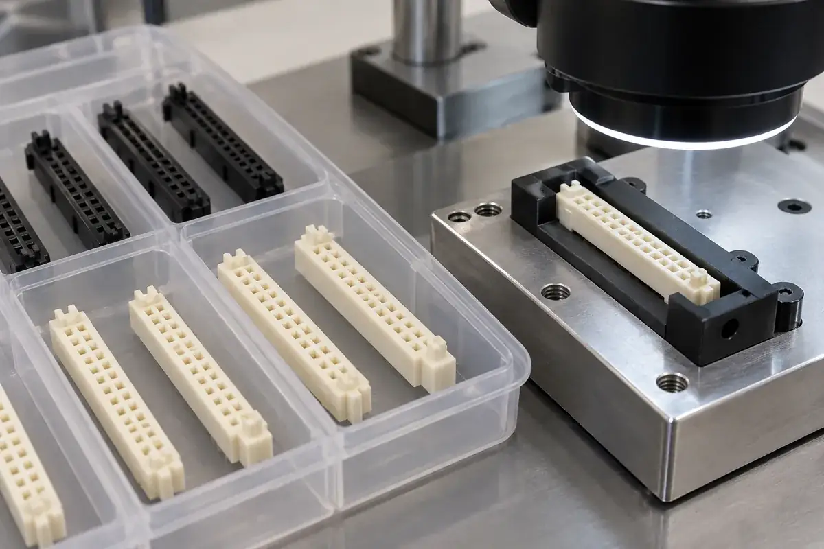
An inspection report can contain many precise numbers and still fail to explain why a board-to-board housing will not mate. The missing link is often the relationship between measured features, assembly references and the mold cavity that produced the sample. More dimensions do not automatically create better evidence if they are disconnected from the actual interface.
A useful plan begins with the assembly questions: will the housing seat on the board, align with its counterpart, guide the contacts and stop at the intended position? It then selects measurements and combined checks that address those questions. The report should allow a failed result to be traced back to a physical feature and an identified production source.
Product design illustrations accompany the engineering explanations below.
Translate each function into a measurable relationship
The seating system establishes the housing's position relative to the board. Inspection may need the location and condition of feet, pegs or other mounting features. The mating system establishes the counterpart relationship, so guide profiles and their position relative to the mounting references matter. These are linked requirements, not two unrelated lists of dimensions.
Contact cavities add a local level. Their entrances, retaining shoulders and final stops may need separate checks because each controls a different part of contact installation. A single cavity-width measurement cannot establish all three functions. The contact-cavity retention guide provides the assembly sequence that helps select the relevant features.
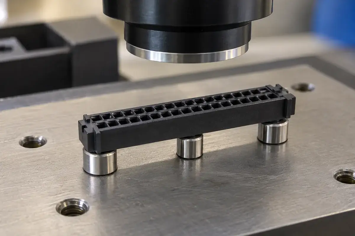
For every selected characteristic, record the physical feature, datum relationship, sample state and method. This makes the requirement reproducible and helps identify when a measurement is not feasible with the proposed access. An internal shoulder may require a different approach from an outside guide wall. Resolve that issue before sample approval is scheduled.
Samtec's multi-connector tolerance discussion connects component positions to the complete board arrangement. For inspection planning, that supports checking guide-to-mounting relationships rather than relying entirely on isolated feature sizes. The actual acceptance limits still come from the approved custom design.
Keep mold-cavity identity attached to every result
In a multi-cavity mold, each cavity is a distinct source of geometry even when all cavities share one drawing. Pooling their results can hide a local shift or profile difference. Development samples should remain identified through measurement, assembly evaluation and retention. That allows a functional issue to be compared with the corresponding dimensional evidence.
Part marking is one identification route when the design permits it. Controlled sample trays or other documented methods may be needed when marking space is restricted. The method should survive the handling sequence without confusing cavity identity with sample number. A label applied after several untracked samples have been mixed cannot reconstruct their production origin.
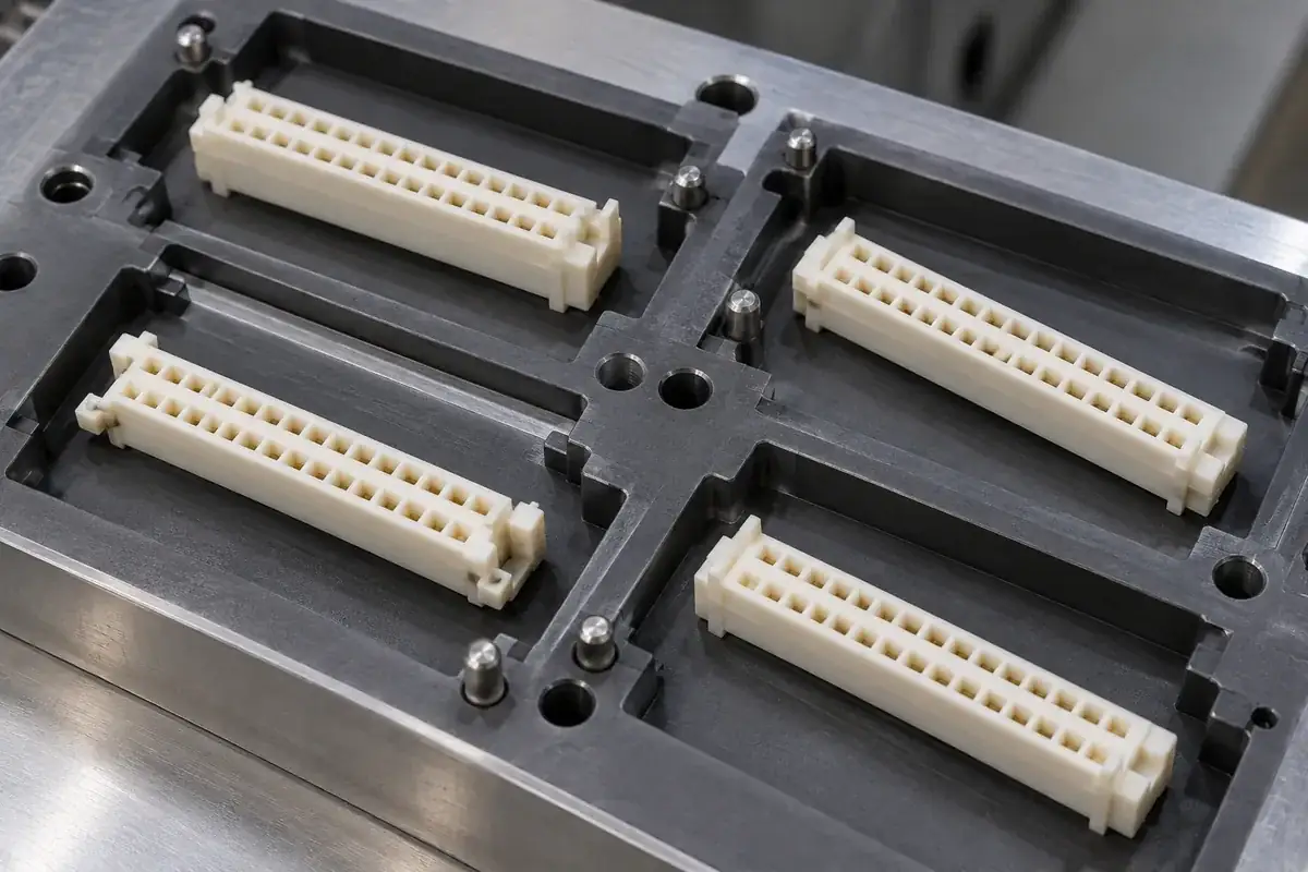
Also retain tool configuration and revision. A replacement core, adjusted guide detail or approved resin change can create a new comparison boundary. Results collected before and after that change should not be blended without explanation. The purpose is not paperwork for its own sake; it is the ability to understand which configuration produced an accepted or rejected interface.
Sampling frequency should follow the approved control plan and the stability demonstrated for the actual process. A successful first sample is not evidence that every cavity is equivalent or that future production is stable. Conversely, measuring every possible feature on every part may be impractical and unnecessary. Select controls around functional risk and demonstrated process behavior.
Define how the fixture changes the part
A long plastic housing can deflect under probing or clamping. A fixture that forces all feet flat may make height measurements repeatable while hiding free-state bow. If the requirement is for a mounted condition, that restraint may be intentional. If the requirement is free-state geometry, it can invalidate the result. State the condition explicitly.
Optical measurement avoids some contact forces but still depends on support, focus, edge definition and the selected view. A shadow or chamfer can create an apparent edge different from the controlling surface. Agree which section or boundary represents the drawing feature. A measurement method is only useful when it observes the geometry that the requirement actually describes.
The warpage and functional-fit guide separates free and constrained states. Use that distinction in the inspection plan rather than treating fixture setup as a minor laboratory detail. The same part can legitimately produce different measurements in different states; the report must identify which state is governed by acceptance.
Measurement capability should be assessed against the required decision. Repeatability on a convenient large feature does not prove capability on a narrow internal shoulder. Where access or contrast is difficult, consider a different method, sectioned development sample or an agreed combined check. Any destructive or indirect method should be identified so its evidence is interpreted correctly.
Use fit checks as controlled evidence
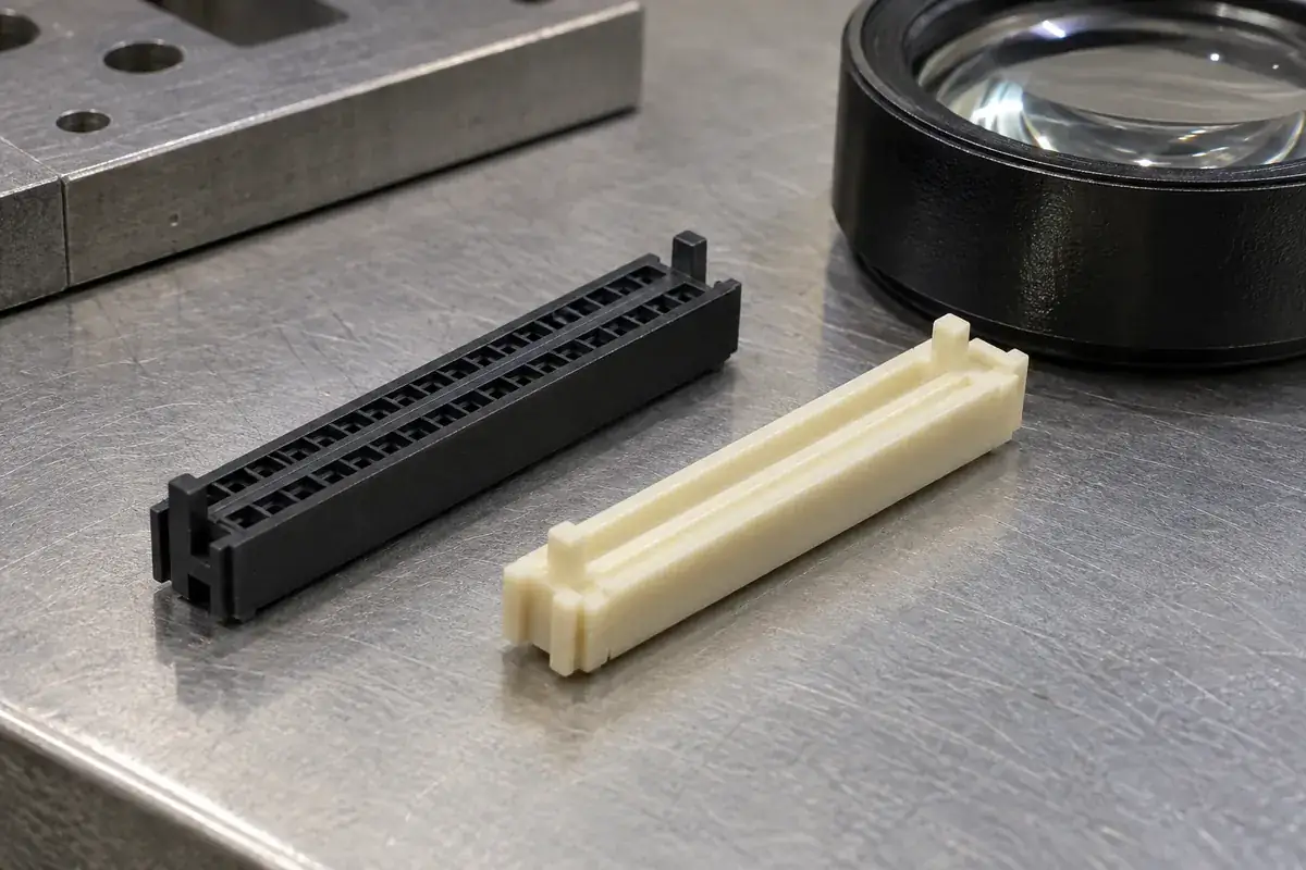
A functional master can evaluate several relationships at once, such as guide entry and final seating. Its value depends on its defined geometry, support and condition. An untracked counterpart from a parts bin may provide a useful troubleshooting clue, but it is not automatically an acceptance gauge. Preserve the reference that produced the result.
Define the permitted approach and stopping condition for the check. If an operator can tilt, squeeze or repeatedly reposition the housing until it passes, the result may not represent production assembly. A check should reproduce the freedom that the real process permits. It should also avoid adding forces or constraints that the approved assembly never applies.
When a fit check fails, retain the sample and compare its local measurements before changing the mold. A large cavity opening, misplaced guide, proud gate witness and bowed base can produce similar symptoms through different mechanisms. A short diagnostic chain is more useful than a long report that only confirms the outside dimensions are nominal.
For custom board-to-board housing supply, agree the inspection plan alongside the drawing and sample schedule. The broader connector insulator scope establishes the component boundary. Acceptance then connects identifiable molded parts to reproducible measurements and defined assembly evidence, without assigning untested performance to the completed electrical connector.