
Precision connector components · Made to your design
Custom Pin Header and Socket Insulator Bases
Define how the plastic base locates each contact and supports the next assembly step.
FECISION coordinates injection molding for drawing-defined pin-header insulating strips, socket contact housings and spacer bases. Share the plastic drawing together with the pin or socket-contact geometry. We review the contact interfaces, support surfaces and installation sequence to prepare a tooling, sample and production scope.
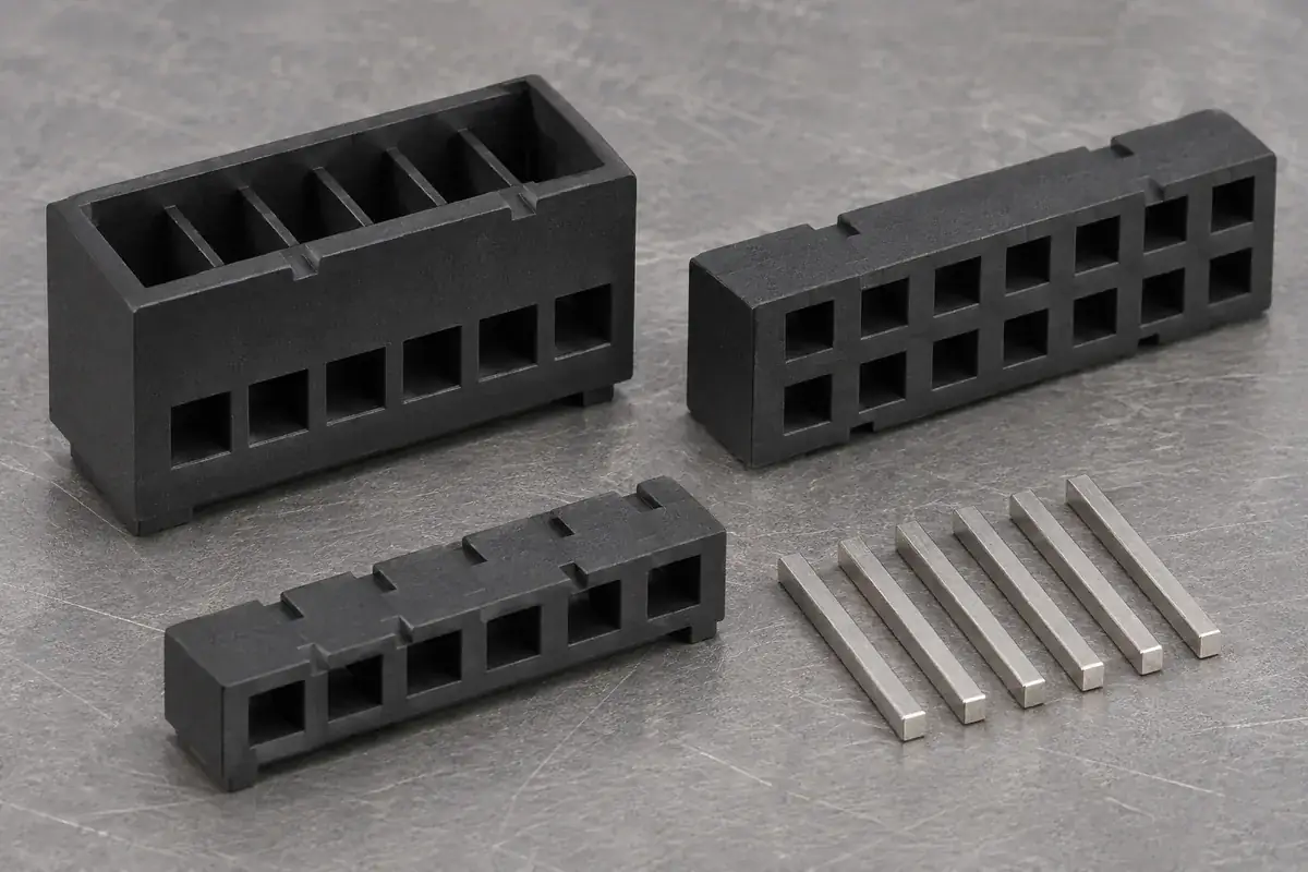
Product details
Explore the contact holes, support faces and spacing features
These product design illustrations show the plastic components around a pin-and-socket assembly. Your drawings define the contact fit, finished position and inspection references.
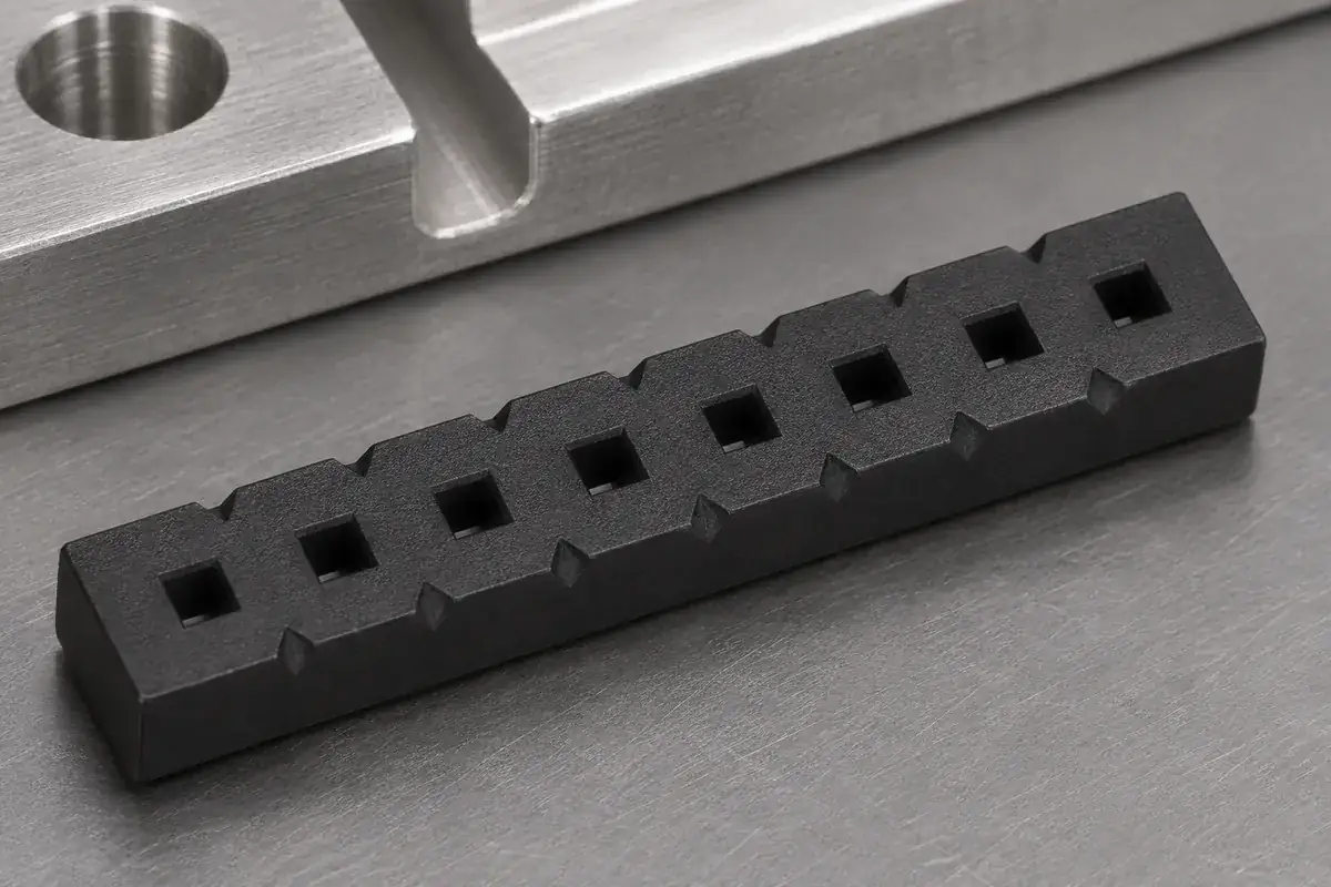
Pin-support hole pattern
Product design illustration: define the hole profile, orientation and locating relationship to the specified metal pin.
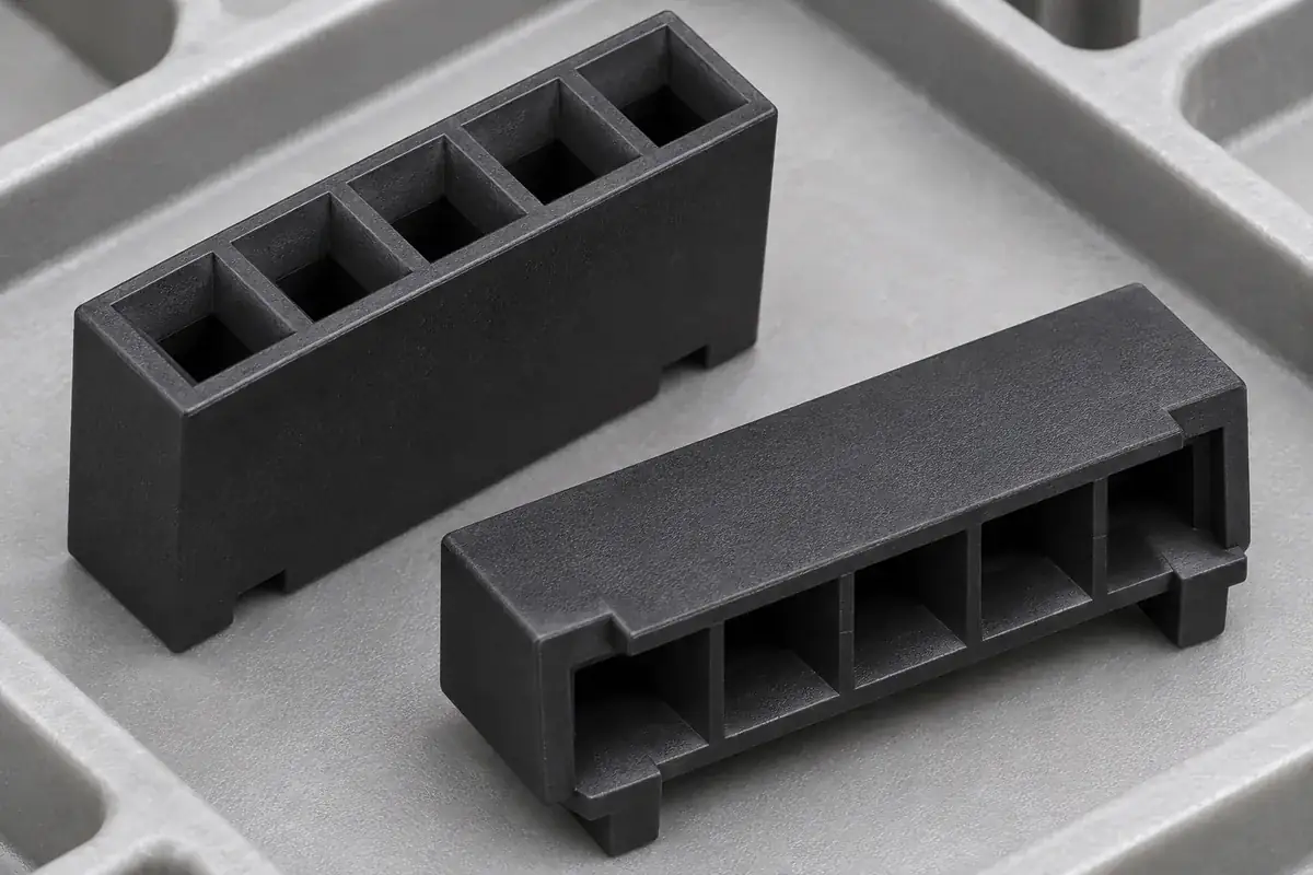
Socket contact cavities
Product design illustration: review the contact-entry path, retention details and space needed for the socket contact to work.
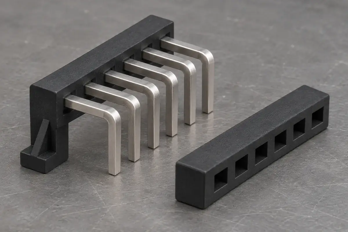
Right-angle support
Product design illustration: relate the molded support position to the pin bend, assembly direction and required exposed lengths.
Separation features
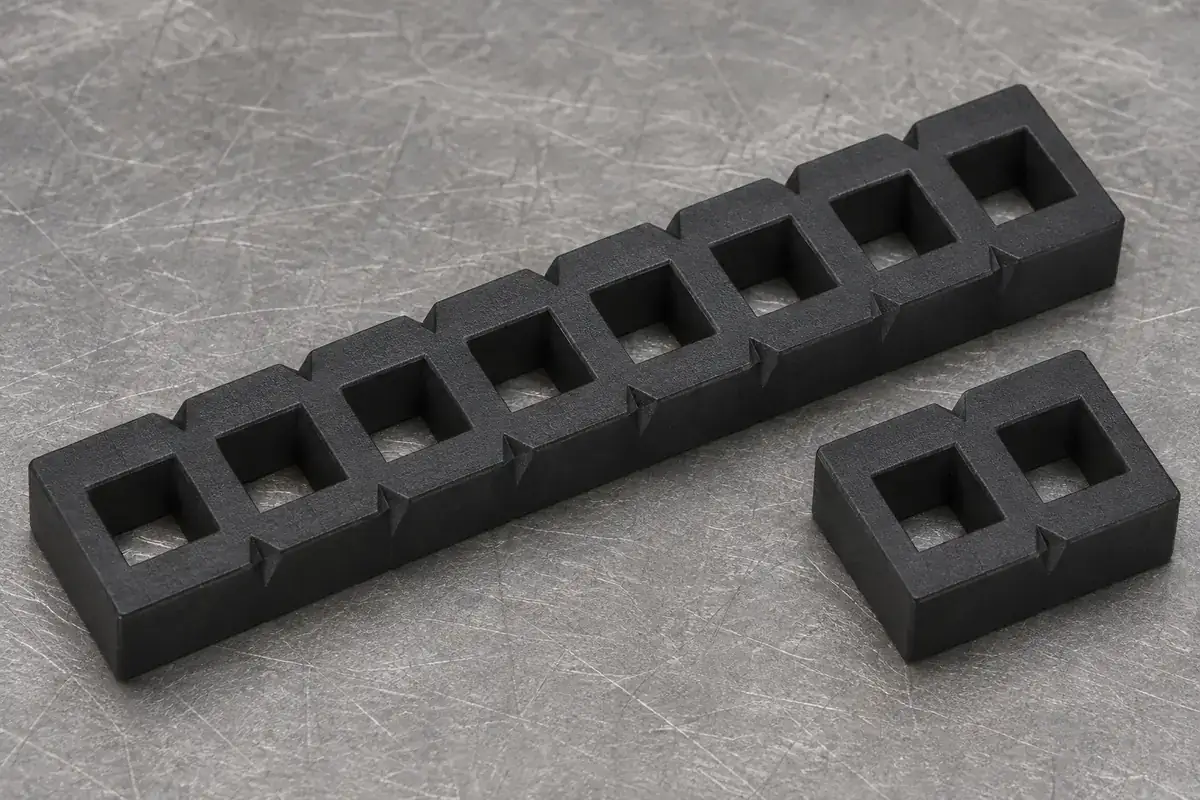
Product design illustration: review the separation station and the usable material remaining around the end contact.
Two support planes
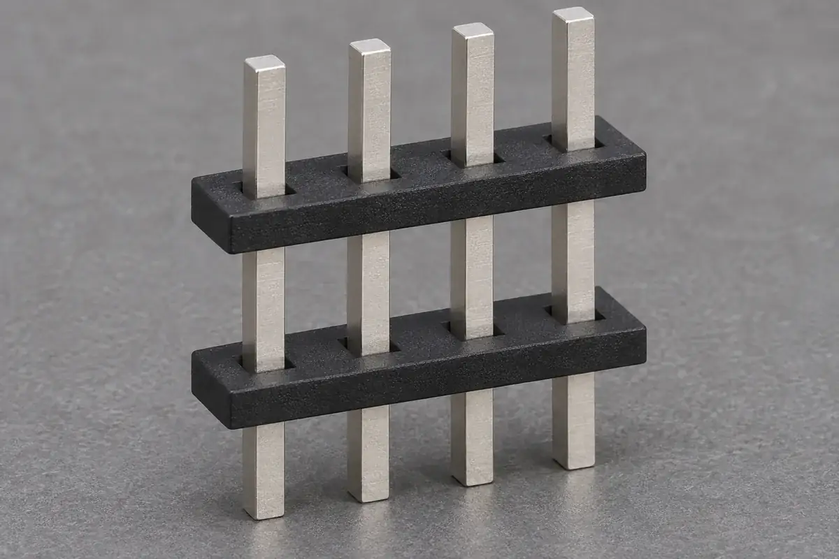
Product design illustration: specify both body positions and their relationship to the exposed contact ends.
Illustrative configurations. Final specifications follow your approved drawings.
Application fit
Molded bases for pin and socket contact arrangements
A header base positions the metal pins relative to one another and to its mounting references. A socket insulator also surrounds the receiving contacts and defines their entry and retention space. The contact construction, assembly process and board interface determine which molded features matter most. This page focuses on those insulating bases and spacer strips, including configurations with exposed pins or separate socket contacts.
Pin-header insulating strips
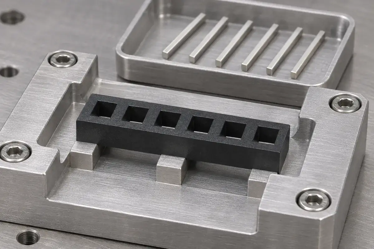
Single- and multi-row bases with drawing-defined pin holes, body height and locating surfaces. Review the pin cross-section, its orientation and any retention features with the molded opening. For a strip that will be cut or separated into shorter sections, include the intended finished lengths and the condition allowed at the new ends.
Socket-contact insulating bodies
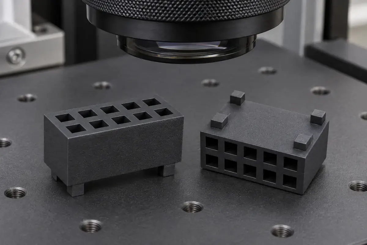
Molded bodies with individual contact cavities, entry lead-ins and contact-retaining details. Supply the metal socket contact as well as the mating pin definition. The plastic cavity must accommodate installation and the intended contact action while maintaining the specified contact location within the body.
Right-angle and offset support bases
Insulators for assemblies in which the contact changes direction between its mating end and board termination. Define where the bend sits relative to the plastic, which end is installed first and how the body is supported during forming or contact loading. Those decisions influence access, hole entry and the surfaces available to the assembly fixture.
Spacer and dual-insulator arrangements
Separate molded bars that establish additional support planes along a contact array. Specify each bar location, the required exposed lengths and the reference used to set their separation. Evaluate the complete arrangement so small hole-pattern differences do not bend the pins or make the second bar difficult to install.
Quote-ready inputs
What to send for a meaningful quotation
Use the same drawing and requirements for every proposal. Mark open decisions explicitly so that a low price does not conceal a different deliverable.
| Area | Please provide | Review before release |
|---|---|---|
| Plastic and contact definition | Base CAD and drawing revision, pin or socket-contact drawing, row layout and intended variants. | Relate hole profiles, retaining details and locating faces to the actual metal component. |
| Body position and exposed length | Mating-end projection, board-tail projection, body height and any second-insulator position. | Identify the assembly stops and datums that establish these dimensions together. |
| Assembly process | Contact-loading direction, forming sequence, strip separation and fixture approach. | Provide support lands and travel clearance at each stage, including access after pins are installed. |
| Material and exposure | Approved resin grade or candidate requirements, color, soldering profile and cleaning chemistry. | Evaluate the selected grade and molded geometry under the agreed process and service conditions. |
| Molding and inspection limits | Critical openings, flash restrictions, gate and ejector locations, standoff height and permitted end condition. | Agree how the empty molded base is measured and how the assembled contact pattern is checked. |
| Demand and supply format | Trial quantities, repeat demand, finished position counts, packaging and approval timing. | Compare dedicated lengths and separation-based supply against handling and inspection requirements. |
From drawing to approval
Develop the base around the contact-loading sequence
Define the interfaces and references
Start with the plastic and metal drawings together. Identify the support faces, retained contact region, mating end and board termination. Resolve whether a dimension is controlled on the empty molded base, during contact installation or on the completed assembly. This prevents a hole dimension from being used as a substitute for a finished pin-position requirement.
Review molding and assembly access
Assess small core features, wall transitions, parting lines, gate placement and ejection against the functional openings. Review the support nest and contact-loading direction at the same time. A base that fills well in the mold still needs accessible surfaces to react assembly forces without loading thin lips or separation reliefs.
Evaluate the identified sample configuration
Inspect empty bases using agreed references, then install the specified pins or socket contacts under the planned conditions. Check body location, exposed lengths and relevant mating or board interfaces. For separated strips or dual-insulator assemblies, include those actual operations in the sample evaluation and record which component revisions were used.
Release the component and supply format
Confirm the approved plastic drawing, resin, contact definition, tooling state and packaging. Record which dimensions are controlled during molding and which belong to subsequent assembly. Changes to pin cross-section, bend position, resin or separation method can then be evaluated against the approved configuration before repeat production.
Practical engineering and buying guides
Decisions to make before production
- Pin Header and Socket Insulators: What Each Plastic Base DoesCompare pin-header bases and socket insulators through contact support, entry guidance, retention and assembly references before specifying a custom molded part.
- Straight vs Right-Angle Headers: Where Plastic Support MattersReview straight and right-angle pin-header bases through force direction, bend support, board seating and fixture access before changing a molded support feature.
- Pin Header Exposed Length: Base Height, Stops and SeatingUnderstand how pin length, insulator height, body position and board seating combine to determine mating exposure and solder-tail projection in a pin header.
- Why a Pin Header Insulator Slides Along Its PinsDiagnose pin-header body movement by separating configured position from unintended drift, then examining retention geometry, assembly support and process exposure.
- Breakaway Pin Header Cracks: Reviewing the Separation FeaturesTrace cracks after cutting a breakaway pin header through notch placement, remaining end-wall thickness, fixture support and inspection of the separated section.
- Rotated Square Pins: Why Header Insulator Holes Can CrackInvestigate square-pin orientation, hole corners, retention features and insertion support before changing a cracked pin-header insulator or its material.
- Supporting a Pin Header Base During Pin InsertionPlan pin-header insertion tooling around the load path, supported plastic faces, tail clearance and seating reference rather than pressing against thin edges.
- Bend Pins Before or After Fitting the Insulator?Compare pin forming before and after base installation through tooling access, reaction forces, locating references and final right-angle header geometry.
- Pin Header Board Standoff: Soldering and Cleaning AccessReview pin-header board clearance through molded feet, solder-tail projection, joint visibility and cleaning paths without treating one gap as a universal rule.
- Dual Pin Header Insulators: Alignment and Assembly HeightDefine two insulator positions on a shared pin array using functional references, controlled support and free-state inspection of alignment and exposed lengths.
Related connector manufacturing scopes
Explore empty insulating bodies, components molded around metal terminals and the precision mold inserts used to form them. Each scope has its own drawings and acceptance requirements.
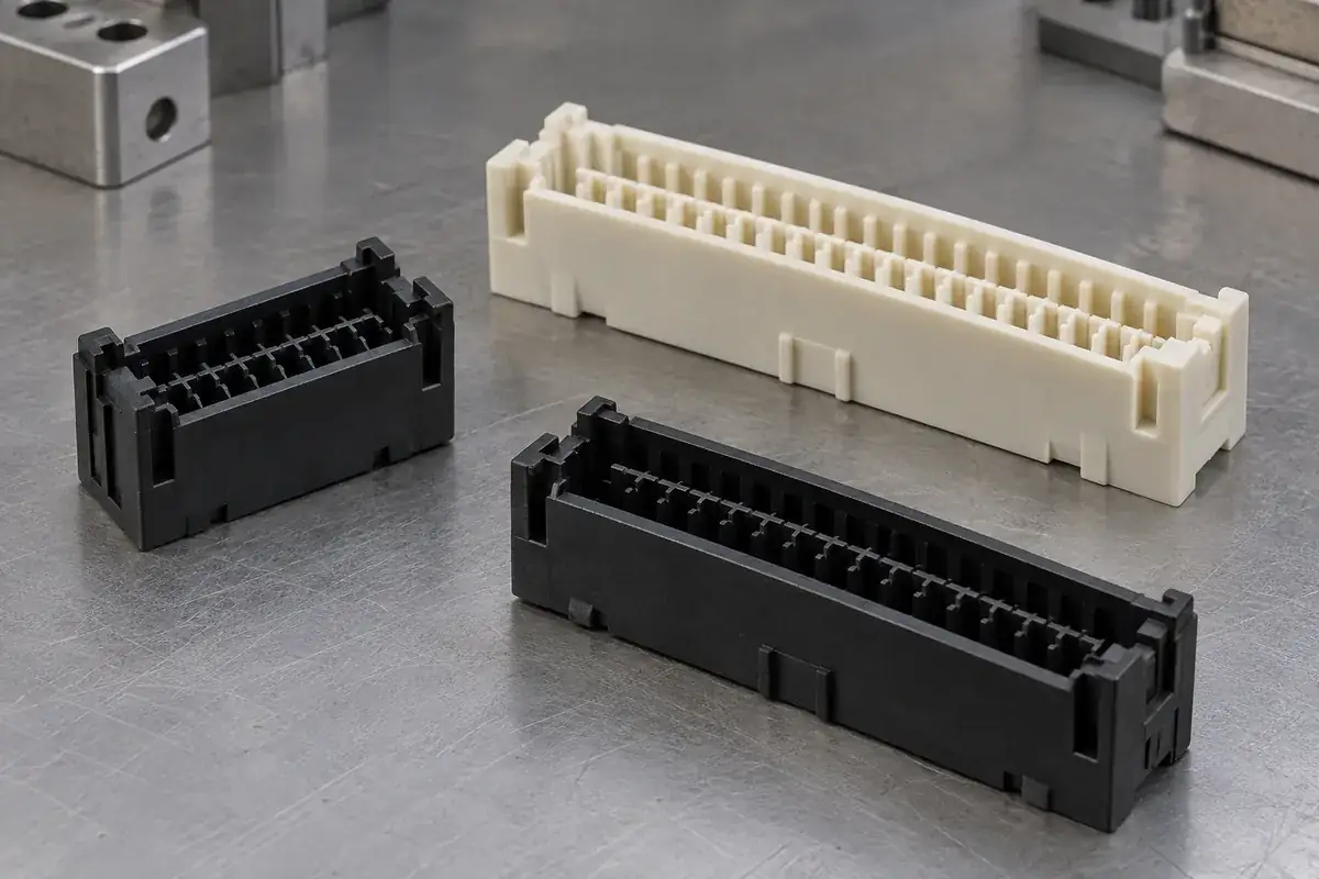
Custom Board-to-Board Connector Housings
Custom molded board-to-board connector housings. Review stack height, alignment, contact cavities, mounting features and inspection with FECISION.
Review the application →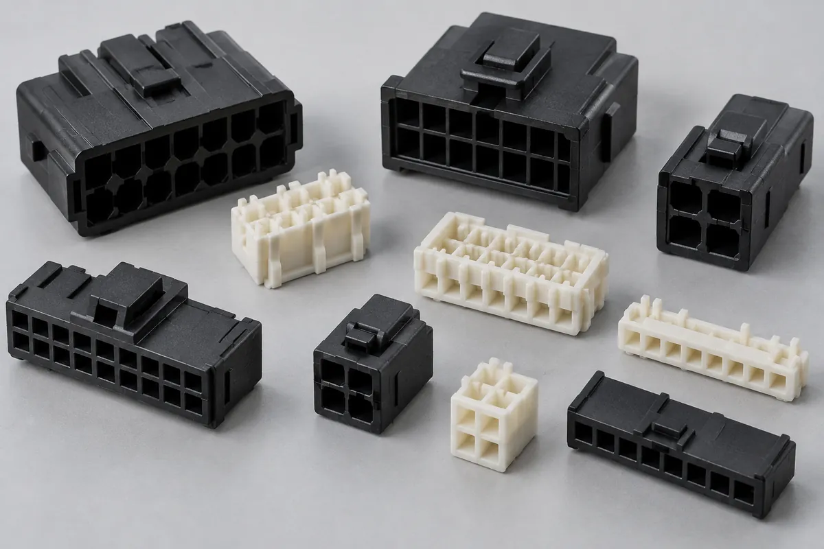
Connector Insulators & Terminal Carriers
Custom molded insulating bodies and terminal carriers. Define terminal interfaces, locating references, exact resin and component acceptance.
Review the application →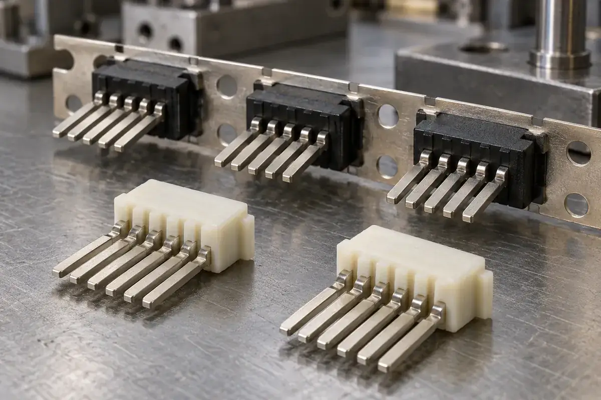
Custom Insert-Molded Connector Components
Custom connector components combining stamped terminals and molded plastic. Review contact location, carrier strips, resin shutoffs, tooling and inspection with FECISION.
Review the application →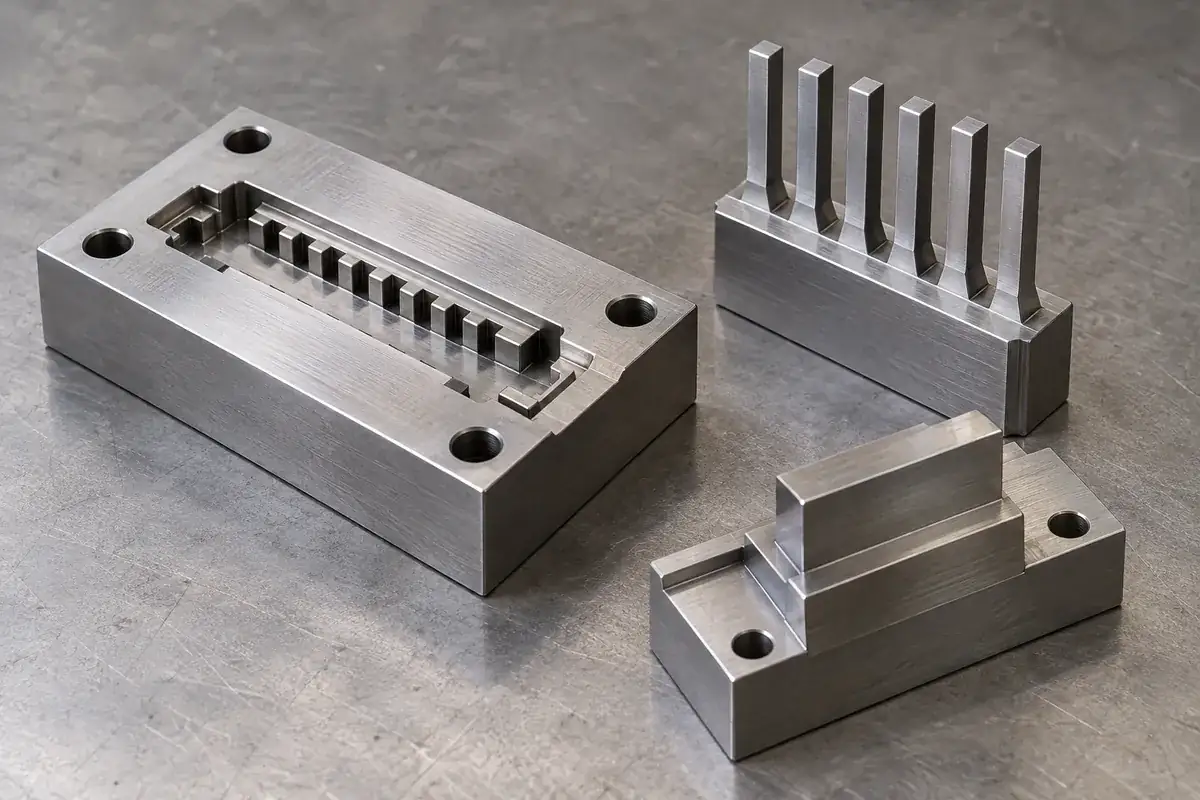
Precision Connector Mold Inserts
Custom steel mold inserts for connector tooling: cavity inserts, thin cores and comb features. Review drawings, locating fits, finishing and replacement scope with FECISION.
Review the application →Before you request a quote
What information is needed for a custom insulator quotation?
Send the plastic CAD and dimensioned drawing, the pin or socket-contact definition, required body positions and the assembly sequence. Add resin requirements, quantities, finished position counts and the inspection evidence you need. A sample or assembly photograph can help explain fixture access alongside the controlled drawings.
How does a header base differ from a socket insulator?
The header base locates pins and supports their specified position. A socket insulator provides cavities for receiving contacts, including the space needed for their installation and contact action. The drawings should identify which features retain the metal part and which guide the mating contact.
Can straight and right-angle headers use the same base?
That depends on the contact geometry and installation sequence. The relevant hole profile may be shared, while bend clearance, support position or fixture access differs. Provide both assemblies so a common molded base can be reviewed against the complete process for each configuration.
Can the insulator position be selected along the pin length?
The finished body position can be specified as part of the assembly definition when the contact and retention construction support it. Agree the stop references, exposed lengths and process used to achieve that position. A movable body during assembly does not automatically mean that movement is acceptable in the finished connector.
Can insulating strips be supplied in different position counts?
Provide the required lengths and demand split. Dedicated molded lengths and strips intended for later separation create different tooling, handling and end-condition requirements. The review will consider the separation feature, nearby contact support and inspection of the finished end.
How is the resin chosen for soldering and cleaning exposure?
Use the approved grade where one is specified. For a new design, provide the actual thermal profile, loading condition, cleaning process and required function afterward. Candidate material data supports selection; the molded base and assembled contact arrangement are evaluated under the agreed application conditions.
What should be checked on a two-insulator assembly?
Define both body positions, the exposed contact lengths and the locating relationship between the two hole patterns. Evaluate loading and support so the second bar does not force an unintended bend into the pins. Inspection should distinguish the empty molded features from the resulting assembled alignment.
Your next step
Discuss the part with its intended function.
Send the insulating-base drawing with its contact geometry and assembly sequence. We will review the molded interfaces, sample plan and production requirements for your custom pin-header or socket components.
Explore our connector injection molding service or review other connector components and mold inserts.