
Precision connector components · Made to your design
Custom TPA and CPA Connector Secondary Locks
Connect the small molded lock to the terminal, housing and assembly states it must control.
FECISION coordinates injection molding for custom TPA inserts, CPA sliders and related connector retainers. Share the lock drawing and its mating components. We review the retaining interfaces, travel, material and assembly access to define tooling, samples and component inspection.
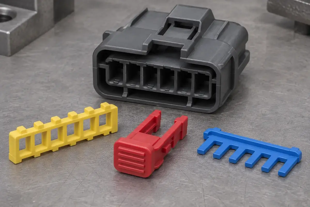
Product details
See the features that guide, retain and release a secondary lock
These product design illustrations show molded locking shoulders, rails, detents and service openings. Your component drawings and assembly sequence define how those features work together.
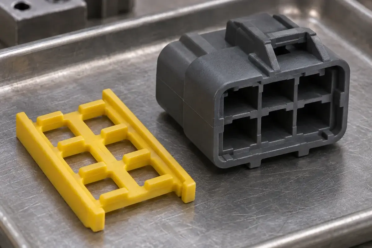
TPA retaining interfaces
Product design illustration: relate the retaining shoulders and clearance windows to the terminal and housing definitions.
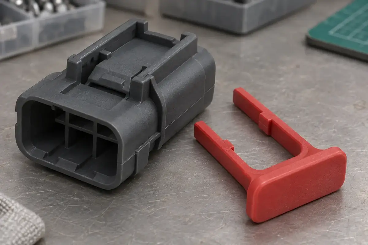
CPA slider and push pad
Product design illustration: define how the slider is guided and how its final position relates to the mating latch.
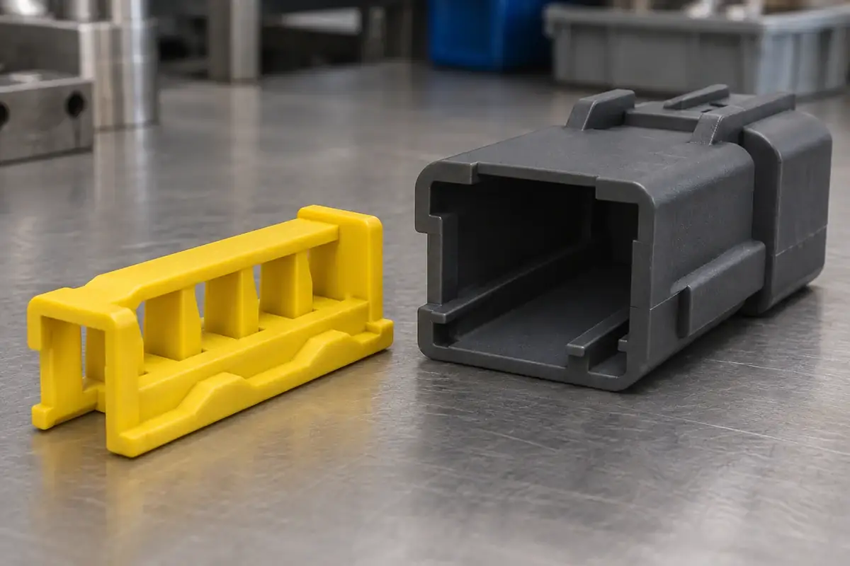
Guide rails and detents
Product design illustration: review the rail, detent and stop surfaces through the intended pre-lock and final-lock travel.
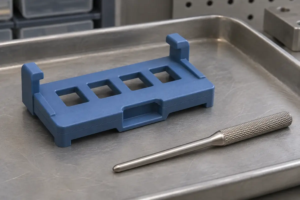
Service access recesses
Product design illustration: provide access to the intended release feature and support the surrounding molded surfaces.
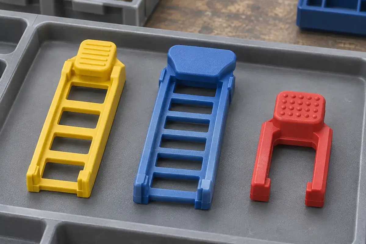
Controlled lock variants
Product design illustration: define each lock variant by its interfaces and drawing revision, including shared and unique features.
Illustrative configurations. Final specifications follow your approved drawings.
Application fit
Custom plastic locks for defined connector interfaces
Terminal position assurance and connector position assurance address different parts of the assembly. A TPA supports terminal retention within a housing; a CPA provides secondary retention at the connector mating interface. The exact geometry and operating sequence are specific to the connector design. Reviewing that distinction early helps assign the right features and approval checks to each molded component.
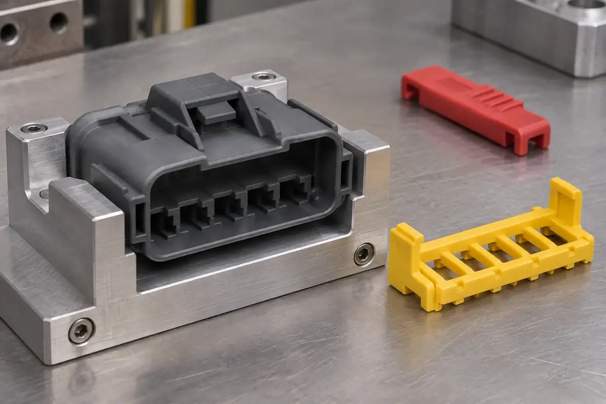
TPA inserts and terminal retainers
Separate molded pieces that interact with the terminal-retention arrangement inside a housing. Review the terminal profile, cavity geometry, permitted seating state and secondary-lock travel together. A retaining window, shoulder or support rib needs a defined relationship to those interfaces. Include the intended terminal population and any empty-cavity arrangements in the assembly review.
CPA sliders and latch retainers
Molded components that act at the mating connector interface. Provide both housing halves and the primary latch definition so the guiding rails, final stop and blocking features can be assessed throughout mating. The review should explain which state permits closure and how the lock is released during authorized service.
Pre-positioned lock components
Separate lock pieces designed to remain attached to a housing during handling or terminal loading. Define the pre-position retention and the later movement into the final state. The tooling and sample review can then address the relevant detents, guiding surfaces and support conditions without confusing handling retention with the finished assembly function.
Lock families and associated molded features
Related secondary locks for a controlled family of connector configurations. Supply the intended cavity counts, housing revisions and demand split. Shared guide spacing or a common push pad may support a tooling strategy, while different terminal layouts or latch positions may require distinct components. Each proposed variant is reviewed against its actual counterparts.
Quote-ready inputs
What to send for a meaningful quotation
Use the same drawing and requirements for every proposal. Mark open decisions explicitly so that a low price does not conceal a different deliverable.
| Area | Please provide | Review before release |
|---|---|---|
| Lock and counterpart definition | Lock CAD and drawing revision, terminal profile, housing drawings and the relevant mating connector. | Identify the retaining contact pairs, guiding surfaces, final stops and assembly references. |
| Assembly and service states | Pre-lock, final-lock and service positions, installation order, operating approach and permitted tools. | Check the full motion and available access, including populated wires, surrounding equipment and fixture support. |
| Material and exposure | Approved resin grade and color or the requirements for candidate selection, including thermal and chemical exposure. | Assess the strain in flexible features, dimensional stability and material evidence needed for the actual component. |
| Feature acceptance | Critical dimensions, flash and gate-vestige limits, functional surfaces and any appearance or identification requirements. | Relate molding and inspection controls to the surfaces that locate, engage or release the lock. |
| Variants and demand | Cavity-count variants, common interfaces, expected quantities, delivery stages and tool ownership requirements. | Evaluate shared tooling details against variant demand while keeping the released component definitions separate. |
| Sample approval evidence | Reference assembly revisions, sample condition, agreed force or travel checks, identification and reporting requirements. | Connect molded-part results to the assembly used for evaluation and agree who approves the completed connector. |
From drawing to approval
Develop the lock around its operating states
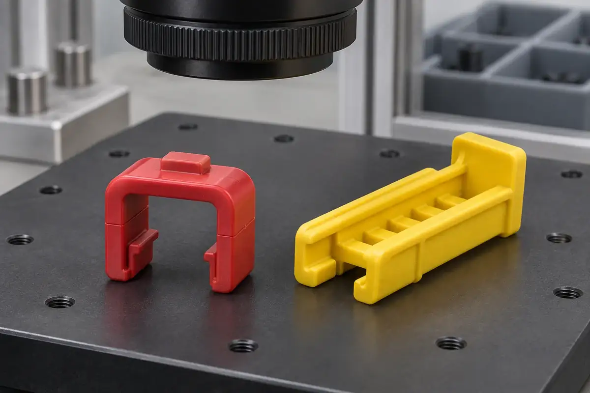
Map the interacting parts
Start with the lock, housing, terminal and relevant mating-half drawings. Identify the retained object, the primary retention arrangement and the secondary lock action. Describe the permitted and blocked assembly states before proposing changes to a rail, window or detent. This gives the molding review a functional baseline.
Review material and mold details
Assess wall transitions, flexible arms, core access, parting lines, gate placement and ejection against the agreed functional surfaces. Discuss how the selected resin and molding condition affect the small component. Features that touch a terminal or control travel need explicit drawing and inspection treatment rather than a general appearance limit.
Evaluate identified samples in sequence
Inspect the molded geometry and review samples with the specified counterpart revisions. Follow terminal loading, pre-lock movement, mating, final closure and service release where applicable. Use the agreed acceptance method for each state; a visible color or an audible click alone does not establish every required interface condition.
Release a controlled component configuration
Confirm drawings, material, tooling state, reference assemblies, packaging and inspection requirements. Record which variants and assembly states were evaluated. Subsequent changes to terminal geometry, housing latches, resin or service tools can then be assessed against that defined configuration before production is continued.
Practical engineering and buying guides
Decisions to make before production
- TPA vs CPA: Two Different Connector Locking ProblemsUnderstand how TPA retains terminals and CPA supports connector mating, then define the plastic interfaces, assembly states and checks each design needs.
- TPA Closed but a Terminal Is Not Seated: What to CheckInvestigate a closed TPA with an unseated terminal by checking component compatibility, seating references, lock travel, damage and assembly conditions.
- Connector Pre-Lock and Final-Lock Assembly SequencePlan connector secondary-lock assembly from the supplied pre-lock state through contact loading, final locking, mating and controlled service release.
- Front- or Rear-Loading TPA? Review Assembly AccessCompare front- and rear-loading terminal locks through contact access, wire population, fixtures and service space before choosing a connector layout.
- Can a TPA Work with Unused Terminal Cavities?Review partly populated connector housings through TPA engagement, empty-cavity treatment, sealing plugs, inspection and controlled harness variants.
- Connector Secondary Locks: Designing Service Tool AccessReduce secondary-lock damage during connector repair by reviewing the release sequence, tool approach, housing support and condition of the locking features.
- Integrated or Separate TPA Locks? Assembly and Service ChoicesCompare integrated and separate TPA concepts through assembly sequence, material needs, molding constraints, repairability and component supply requirements.
- CPA Color and Position: What Actually Confirms Engagement?Use CPA color as a locating aid, then define the mechanical position, viewing direction and inspection evidence needed to confirm connector-lock engagement.
- Can Different Connector Cavity Counts Share a Secondary Lock?Evaluate a shared connector secondary lock by comparing terminal pitch, guide rails, stops, latch interfaces, assembly access and revision control across housings.
- CPA Interlocks: Preventing Closure Before Full Connector MatingReview CPA interlocks through partial mating, primary-latch movement, final stops and tolerance variation before treating a closed lock as mating confirmation.
Related connector manufacturing scopes
Explore empty insulating bodies, components molded around metal terminals and the precision mold inserts used to form them. Each scope has its own drawings and acceptance requirements.
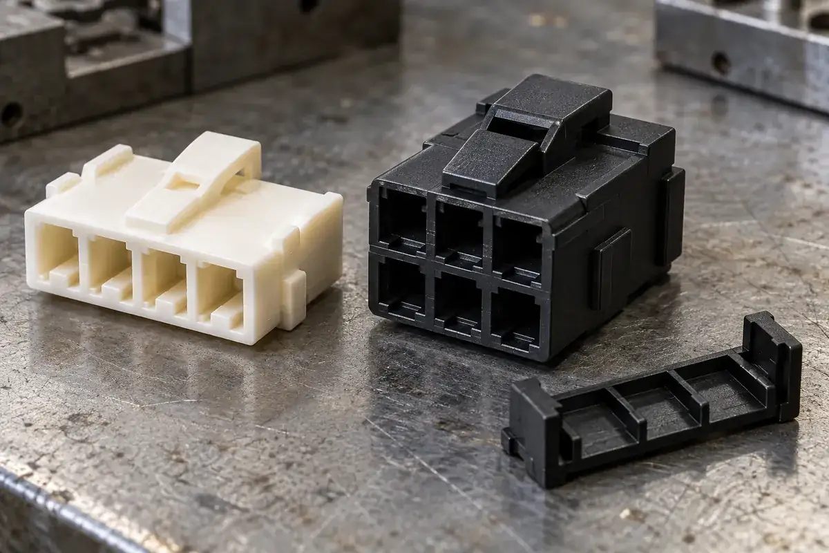
Custom Wire-to-Board Connector Housings
Custom injection-molded wire-to-board connector housings. Review crimp-terminal fit, wire entry, latches, keying and tooling for your plastic components.
Review the application →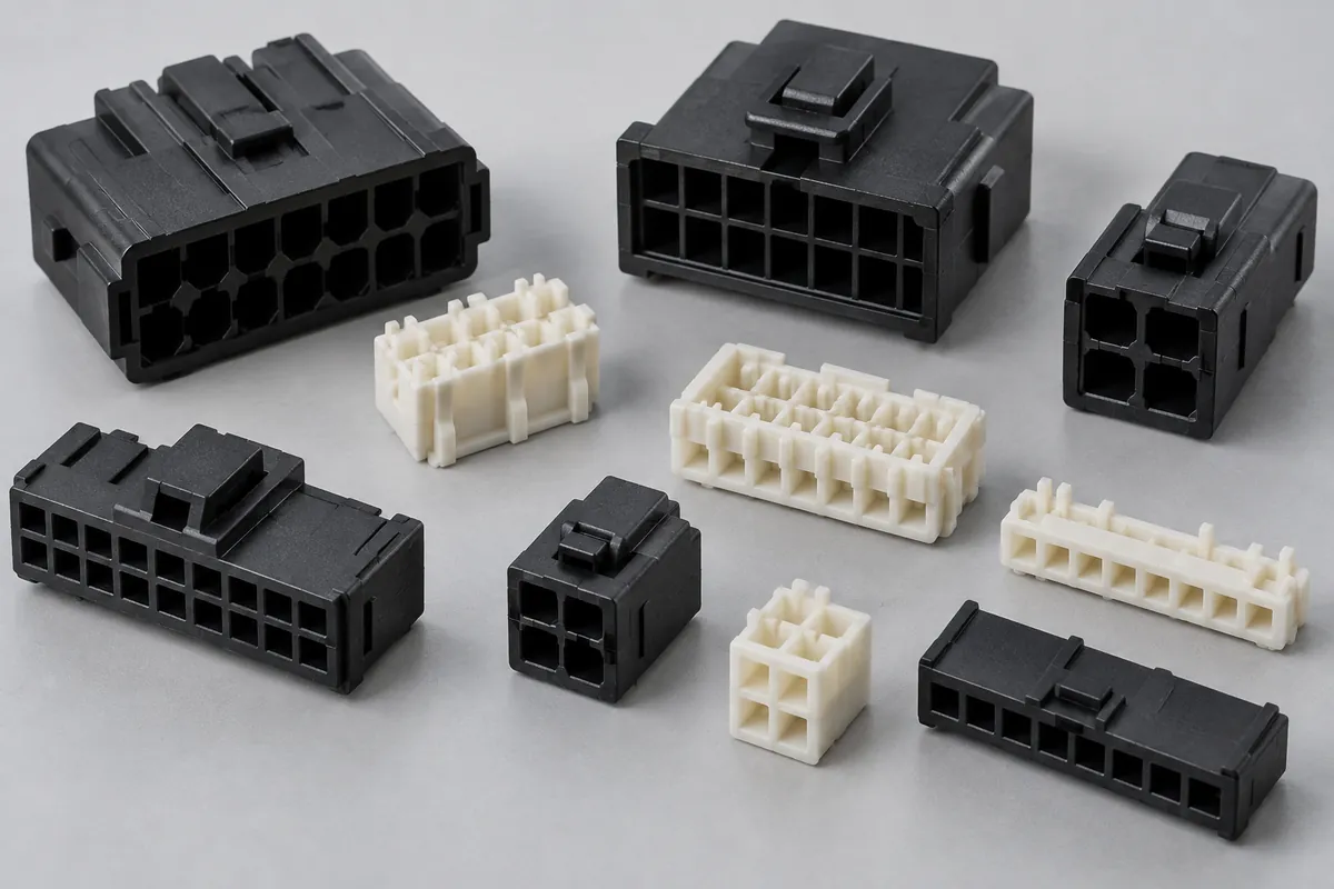
Connector Insulators & Terminal Carriers
Custom molded insulating bodies and terminal carriers. Define terminal interfaces, locating references, exact resin and component acceptance.
Review the application →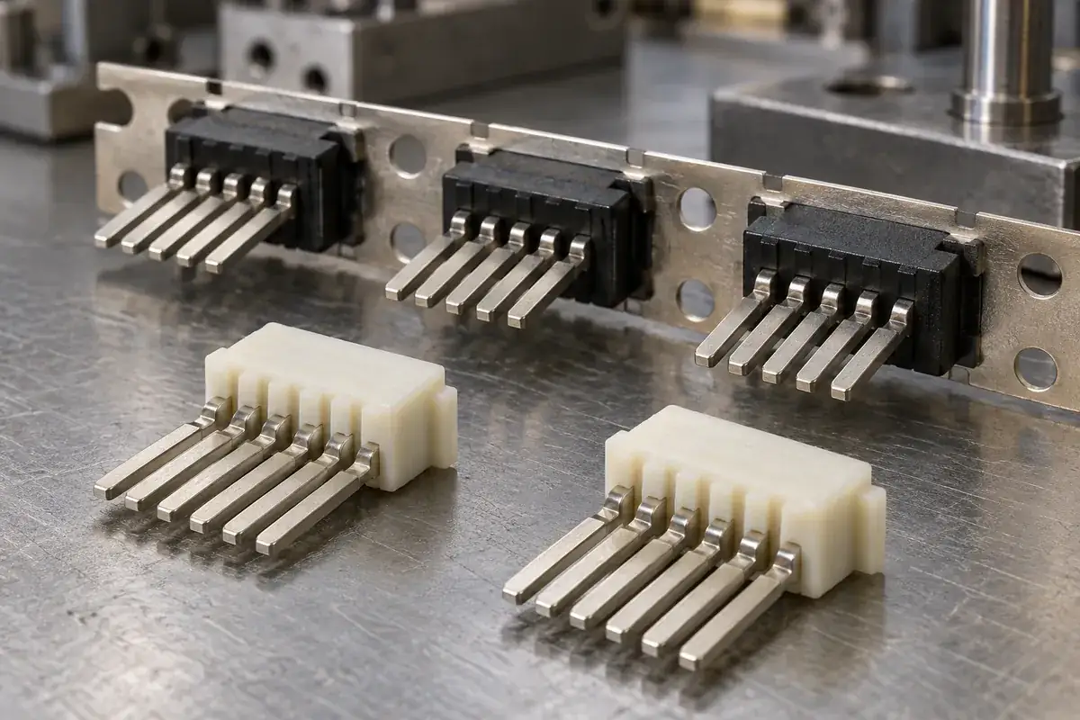
Custom Insert-Molded Connector Components
Custom connector components combining stamped terminals and molded plastic. Review contact location, carrier strips, resin shutoffs, tooling and inspection with FECISION.
Review the application →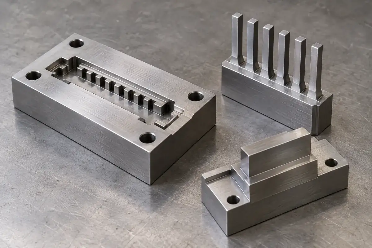
Precision Connector Mold Inserts
Custom steel mold inserts for connector tooling: cavity inserts, thin cores and comb features. Review drawings, locating fits, finishing and replacement scope with FECISION.
Review the application →Before you request a quote
What is the difference between a TPA and a CPA?
A TPA supports terminal retention inside the housing, while a CPA acts at the interface between mating connector halves. Their guides, engagement features and assembly sequence therefore relate to different counterparts. Provide the specific connector definition so the role of each molded component can be reviewed accurately.
What should I send for a custom secondary-lock quotation?
Send the lock model and drawing, the relevant housing and terminal drawings, and the operating sequence. Include material and color requirements, variants, quantity, target assembly checks and the inspection records you need. Reference parts or photographs can help explain access and service conditions alongside the controlled drawings.
Can a secondary lock detect every incompletely seated terminal?
That depends on the specified retention system and its interacting geometry. Define which terminal positions the lock should block, then evaluate those conditions with the correct housing and terminal revisions. The sample plan should distinguish the molded lock dimensions from the intended behavior of the complete assembly.
Can one lock be used across several connector sizes?
Potentially, when the relevant rail spacing, latch position, terminal interface and travel remain compatible by design. Similar color or outside shape is insufficient. Share all proposed variants and their demand so a common lock or tooling approach can be assessed against the complete family.
Which resin is suitable for a TPA or CPA?
Use the approved grade when the connector design already specifies one. For a new component, provide the assembly strain, sustained loads, temperature, chemical exposure and required documentation. The geometry of a flexible arm or rigid retaining shoulder affects the choice alongside the material data.
How should serviceability be included in the design review?
Describe the allowed release sequence, tool geometry, available access and intended reuse conditions. Review the lock with the populated connector where that affects access. Establish which surfaces support the tool and which features are allowed to deflect so sample evaluation reflects the actual service operation.
What is checked before releasing production?
The agreed plan can include functional dimensions, local molding quality, identified material, and assembly checks using controlled counterparts. Define the relevant pre-lock, final-lock and release conditions, sample conditioning and acceptance criteria in advance. Completed-connector qualification is coordinated with the party responsible for that assembly.
Your next step
Discuss the part with its intended function.
Send the lock drawing with its housing, terminal and assembly sequence. We will review the molded interfaces and prepare a tooling, sample and production quotation for your connector secondary-lock components.
Explore our connector injection molding service or review other connector components and mold inserts.