
Precision connector components · Made to your design
Custom IDC Connector Housings and Covers
Keep the cable, contacts and cover aligned throughout the termination sequence.
FECISION coordinates injection molding for drawing-defined IDC insulating bodies, pressure covers and cable-retaining components. Share the plastic drawings with the specified ribbon cable, metal contacts and termination procedure. We review how the molded features locate the cable, support the contacts and establish each assembly state before defining the tooling and sample scope.
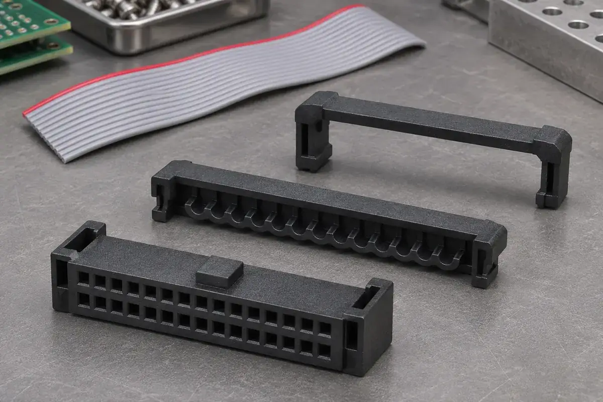
Product details
Explore the housing, pressure cover and cable-support interfaces
Product design illustrations show the molded components around a ribbon-cable IDC assembly. The cable specification, contact geometry and assembly instructions define the actual configuration.
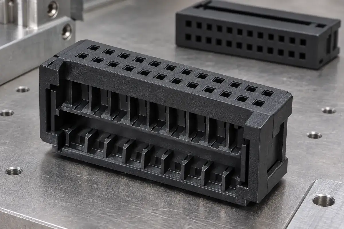
Contact-support body
Product design illustration: define the contact-loading path and the plastic faces that support the specified terminal.
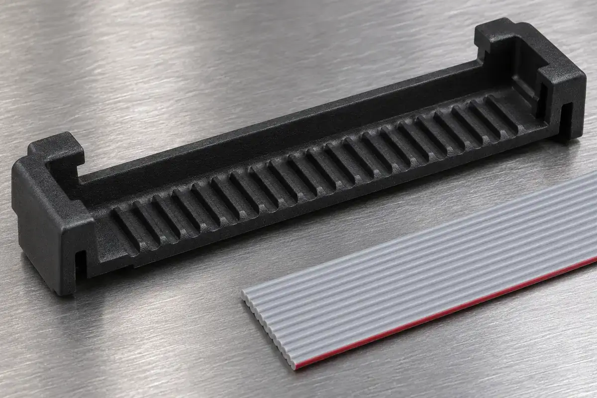
Cable-locating cover
Product design illustration: relate the cover grooves to the cable construction and the termination arrangement.
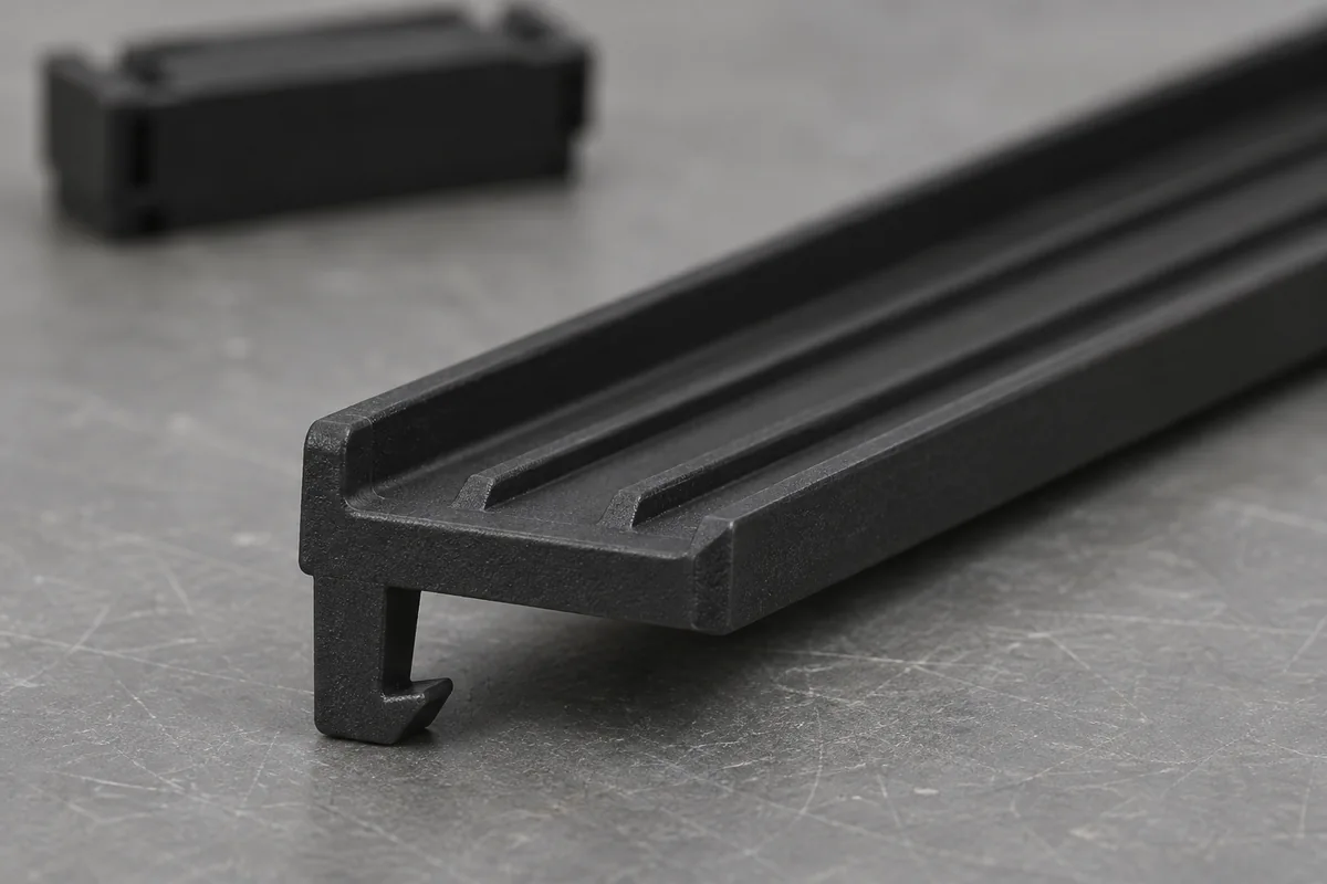
Latch and closure features
Product design illustration: distinguish handling retention, termination travel and the final cover position.
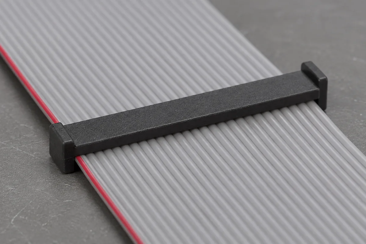
Lateral cable guidance
Product design illustration: review cable width and edge location alongside conductor-to-contact alignment.
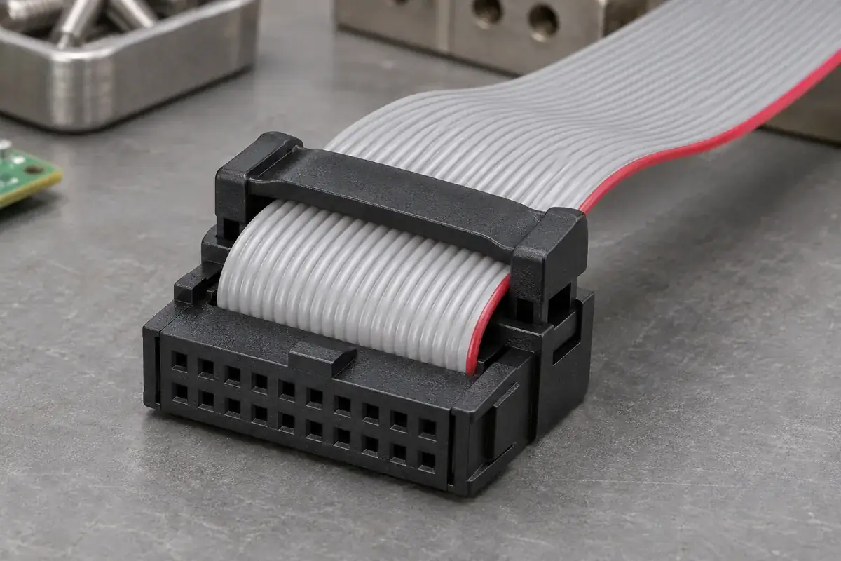
Strain-relief arrangement
Product design illustration: define the cable routing and the features that react handling loads after termination.
Illustrative configurations. Final specifications follow your approved drawings.
Application fit
Molded parts for a defined ribbon-cable termination system
An IDC assembly depends on the relationship between insulated conductors, the terminal arrangement and the tooling that brings them together. The plastic body locates and supports those interfaces; the cover guides and closes over the cable. Define these parts as one coordinated assembly before adjusting an individual groove, wall or latch.
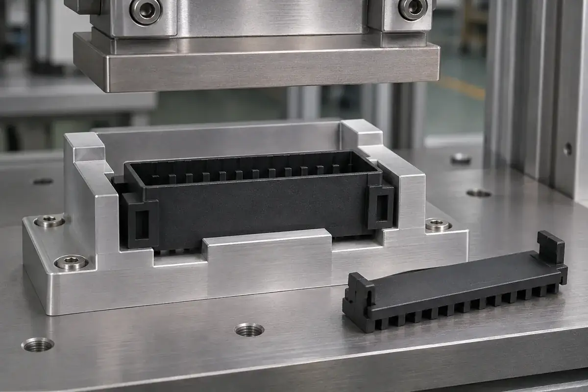
IDC insulating bodies
Custom molded bodies with contact pockets, separating walls, mating-face openings and assembly references. Include the terminal drawing and its installation state so that the cavity and support features can be reviewed against the actual metal component. Identify surfaces where flash or gate vestige would obstruct contact loading or cable termination.
Pressure covers and cable guides
Covers with drawing-defined conductor-locating features, lateral guides and end closures. Review the cable width, conductor spacing, insulation geometry and permitted routing together. A cover that accepts the overall cable width still needs to position each conductor correctly relative to its intended contact.
Preassembly and retention features
Molded hooks, posts and locating features for the specified handling and termination states. Agree whether the cover is supplied loose, retained in a preliminary position or installed later at the termination station. The receiving process and packaging influence how much free movement is useful before the final operation.
Strain-relief bars and cable-retaining components
Separate molded bars or bridges that support a defined cable route after termination. Supply the intended fold direction, space around the connector and handling requirements. The component geometry must be reviewed with the cable assembly, including the access needed to engage and inspect its retainers.
Quote-ready inputs
What to send for a meaningful quotation
Use the same drawing and requirements for every proposal. Mark open decisions explicitly so that a low price does not conceal a different deliverable.
| Area | Please provide | Review before release |
|---|---|---|
| Cable and terminal definition | Cable drawing, conductor arrangement, insulation details, contact drawing and relevant assembly instructions. | Relate the molded locating features to the specified cable and contact combination. |
| Cover states and travel | Loose or preassembled supply state, termination direction, required final position and latch condition. | Review the closure sequence and the references used to confirm completion. |
| Cable routing and support | Exit direction, intermediate connection requirements, foldback path and strain-relief geometry. | Check guidance and retention throughout the actual assembly and handling sequence. |
| Material and molding constraints | Approved resin grade or application requirements, color, exposure and critical surface restrictions. | Assess filling, core details, ejection and dimensional control around functional openings. |
| Inspection and assembly evidence | Plastic feature limits, sample quantities, gauges, termination checks and cable-test requirements. | Separate the molded-part inspection from the evidence needed for the completed connection. |
| Demand and delivery state | Trial order, repeat demand, position-count variants, packaging and approval schedule. | Review tooling and handling options against the required supply format. |
From drawing to approval
Review the molded parts with the cable-assembly process
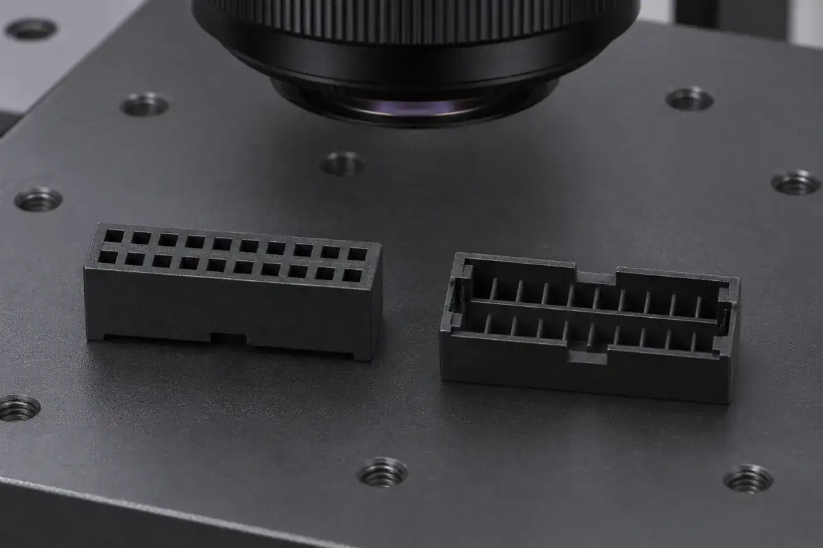
Establish the interface set
Bring the body, cover, terminal and cable revisions into the same review. Identify the cable reference edge, the intended conductor mapping and the surfaces that locate the body in the termination tool. Resolve drawing-view and orientation differences before using a sample as the sole assembly reference.
Review molding and closure
Evaluate walls, core features, latch roots, cable guides and molding access. Check the preliminary and final cover positions against the specified tool approach. The review should distinguish a closure problem caused by molded geometry from one caused by an unsuitable cable or a tool supporting the wrong surface.
Evaluate identified samples
Inspect the molded parts, then assess the specified cable and contacts using the agreed termination process. Record cover position, cable orientation and the relevant mechanical observations. Complete the electrical checks defined for the cable assembly as a separate part of the approval plan.
Release the agreed supply configuration
Confirm component drawings, resin, tooling state, packaging and inspection references. Record the cable and contact versions used for approval. Later changes to cable construction, cover features or termination equipment can then be assessed against a known configuration before repeat production.
Practical engineering and buying guides
Decisions to make before production
- IDC vs Crimp: What the Plastic Connector Housing SupportsCompare IDC ribbon-cable and crimp-terminal housings through wire location, termination forces, contact retention and assembly access for custom molded parts.
- Ribbon Cable Pitch vs Connector Contact LayoutUnderstand how ribbon conductor spacing maps to connector contact rows. Review routing, orientation and molded cable guides before changing an IDC housing.
- IDC Ribbon Cable Pin One: Red Edge, Keys and Housing MarksReview ribbon-cable conductor-one orientation through edge identification, housing marks, polarization and test mapping before releasing an IDC assembly.
- IDC Cover Latches on One Side First: What to CheckInvestigate uneven IDC cover closure through cable seating, tooling support, latch geometry and molded-part condition before changing the assembly force.
- IDC Termination Height: More Than a Closed Cover LatchDefine IDC finished height using the correct housing and cover references. Separate latch engagement, tooling travel and electrical termination acceptance.
- IDC Ribbon Cable Width: Designing the Lateral GuidesReview ribbon-cable width, edge margins and conductor location against IDC guide surfaces. Define a loading window without distorting the cable or cover.
- IDC Ribbon Cable Foldback and Strain-Relief BarsFollow cable loads through an IDC foldback and strain-relief bar. Review bend space, clamp support and service handling without loading the termination.
- IDC Open-Ended vs Closed-Ended Covers and Cable BranchesCompare IDC cable pass-through and end-stop cover layouts for end and intermediate connections. Review routing, loading access and connector-specific limits.
- IDC Preassembled Covers: Holding the Cable-Loading PositionReview the loose preassembled state of IDC covers through retention, cable access, transport protection and controlled travel to the final termination position.
- IDC Assembly Checks: Closure, Cable Position and Electrical TestsSeparate IDC cover closure, conductor location and electrical verification. Build a traceable inspection plan around the actual cable, contacts and tooling.
Related connector manufacturing scopes
Explore empty insulating bodies, components molded around metal terminals and the precision mold inserts used to form them. Each scope has its own drawings and acceptance requirements.
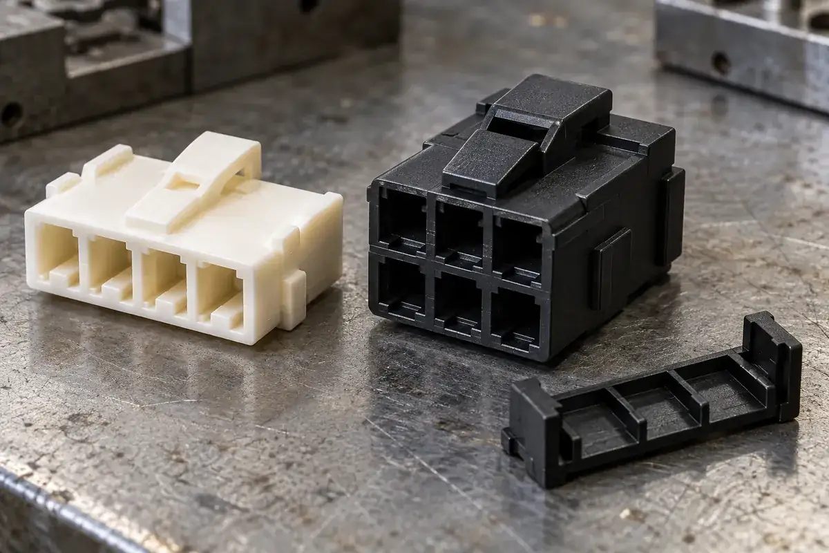
Custom Wire-to-Board Connector Housings
Custom injection-molded wire-to-board connector housings. Review crimp-terminal fit, wire entry, latches, keying and tooling for your plastic components.
Review the application →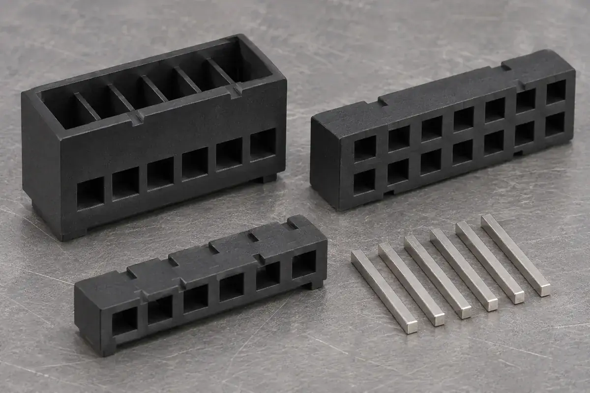
Custom Pin Header and Socket Insulator Bases
Custom molded pin header bases and socket insulators made to drawing. Review pin support, contact cavities, body position, standoffs and assembly requirements.
Review the application →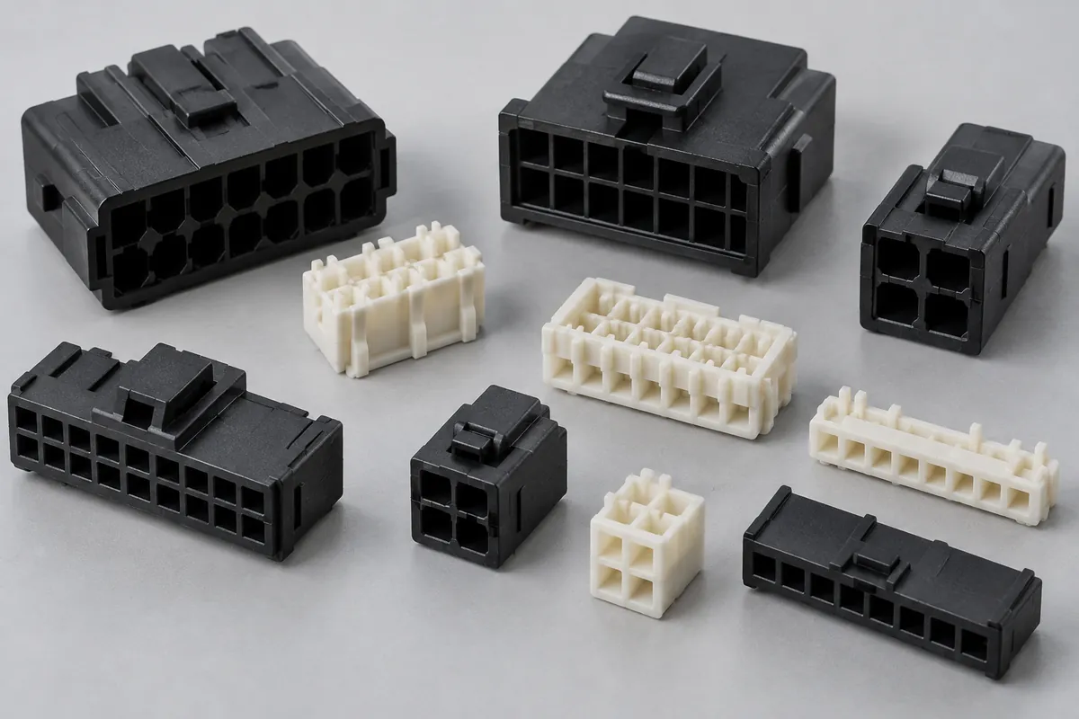
Connector Insulators & Terminal Carriers
Custom molded insulating bodies and terminal carriers. Define terminal interfaces, locating references, exact resin and component acceptance.
Review the application →Before you request a quote
What is needed to quote an IDC plastic component?
Send the plastic CAD and drawing with the specified cable and terminal details. Include the closure sequence, resin requirements, quantities and inspection expectations. Assembly photographs can help explain access and handling, while controlled drawings establish the critical interfaces.
Can the cover be supplied in a preassembled position?
A preliminary retained position can be reviewed where the body and cover are designed for it. Define how the cable is introduced, how the part is packed and what movement remains before termination. Confirm this state separately from the final terminated position.
Does cable pitch define the complete connector layout?
It defines one part of the interface. Conductor spacing, contact arrangement, cavity geometry and the routing used in the termination system must be considered together. Use the actual cable and connector drawings rather than inferring the internal mapping from one nominal dimension.
Can a cover work with different ribbon-cable widths?
Provide the proposed cable constructions and their dimensional limits. Lateral guidance, conductor location and termination travel all need review. A cable fitting between the side walls does not by itself establish that the conductor-to-contact interface is suitable.
Can you review open-ended and closed-ended cover designs?
Yes. Describe whether the connector terminates the cable end or sits along a continuous cable, and show the required cable route. Cover-end geometry, access and strain relief can then be reviewed for that particular assembly.
Is a closed latch enough to approve the termination?
The latch condition is one mechanical observation. The specified final position, cable location and electrical checks have their own acceptance criteria. The approval plan should identify what each observation demonstrates and the assembly state in which it is checked.
How is the material selected?
Provide the approved grade where available, together with handling, temperature, chemical exposure and documentation requirements. For a new design, candidate materials are assessed with the thin walls, latch geometry and required dimensional stability of the actual molded part.
Your next step
Discuss the part with its intended function.
Send the IDC body and cover drawings with the cable, terminal and termination-process details. We will review the molding interfaces, sample plan and required supply state for your custom components.
Explore our connector injection molding service or review other connector components and mold inserts.