
Precision connector components · Made to your design
Custom Terminal Block Housings
Bring the clamp mechanism, conductor path and installation geometry into one molded housing review.
FECISION coordinates injection molding for terminal block housings, partitions and end plates. Share the housing CAD, clamp mechanism and mounting drawing. We review conductor entry, tool access, hardware location and insulating boundaries to define tooling, samples, component inspection and production.
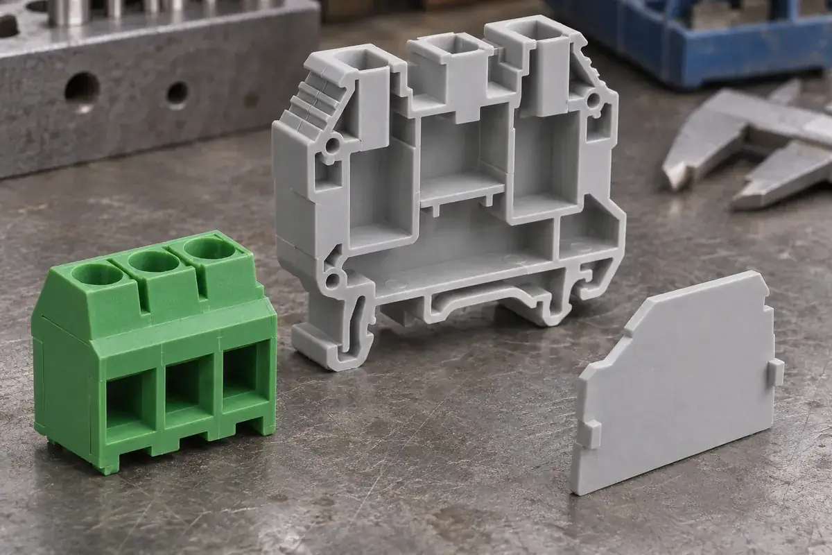
Product details
Explore the housing features around the electrical connection
These product design illustrations show the molded component interfaces: clamp seats, access openings, partitions, joining features and mounting references. The proposed drawings define the geometry for your terminal block design.
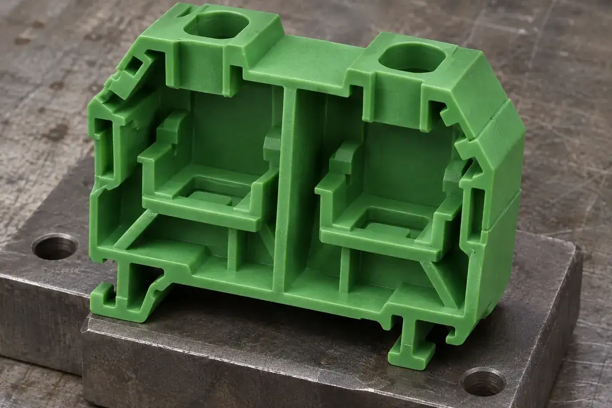
Clamp-mechanism seats
Product design illustration: locate the connection hardware with defined plastic seats and review how assembly loads reach the supporting walls.
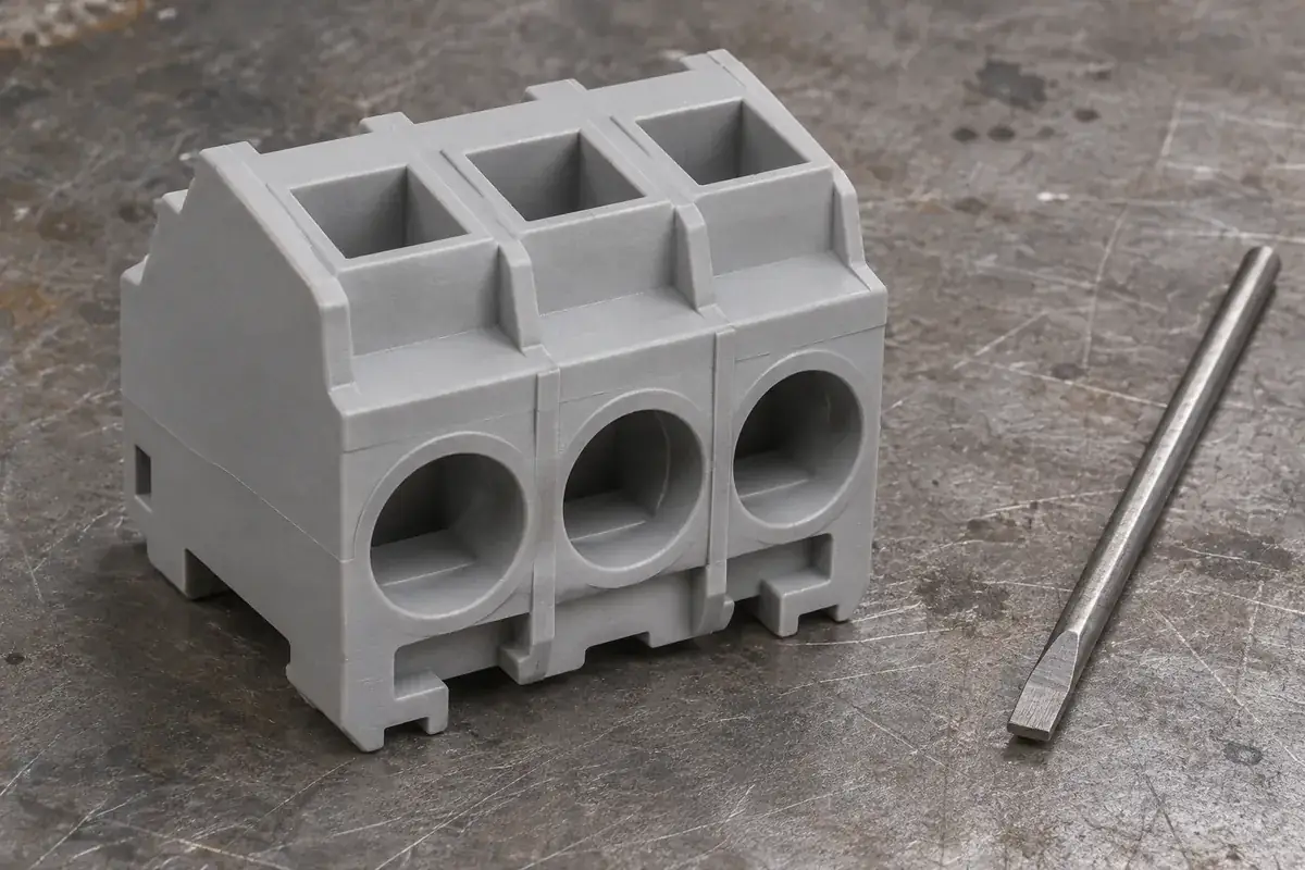
Conductor and tool access
Product design illustration: compare the conductor-entry envelope and operating-tool path in the installed orientation.
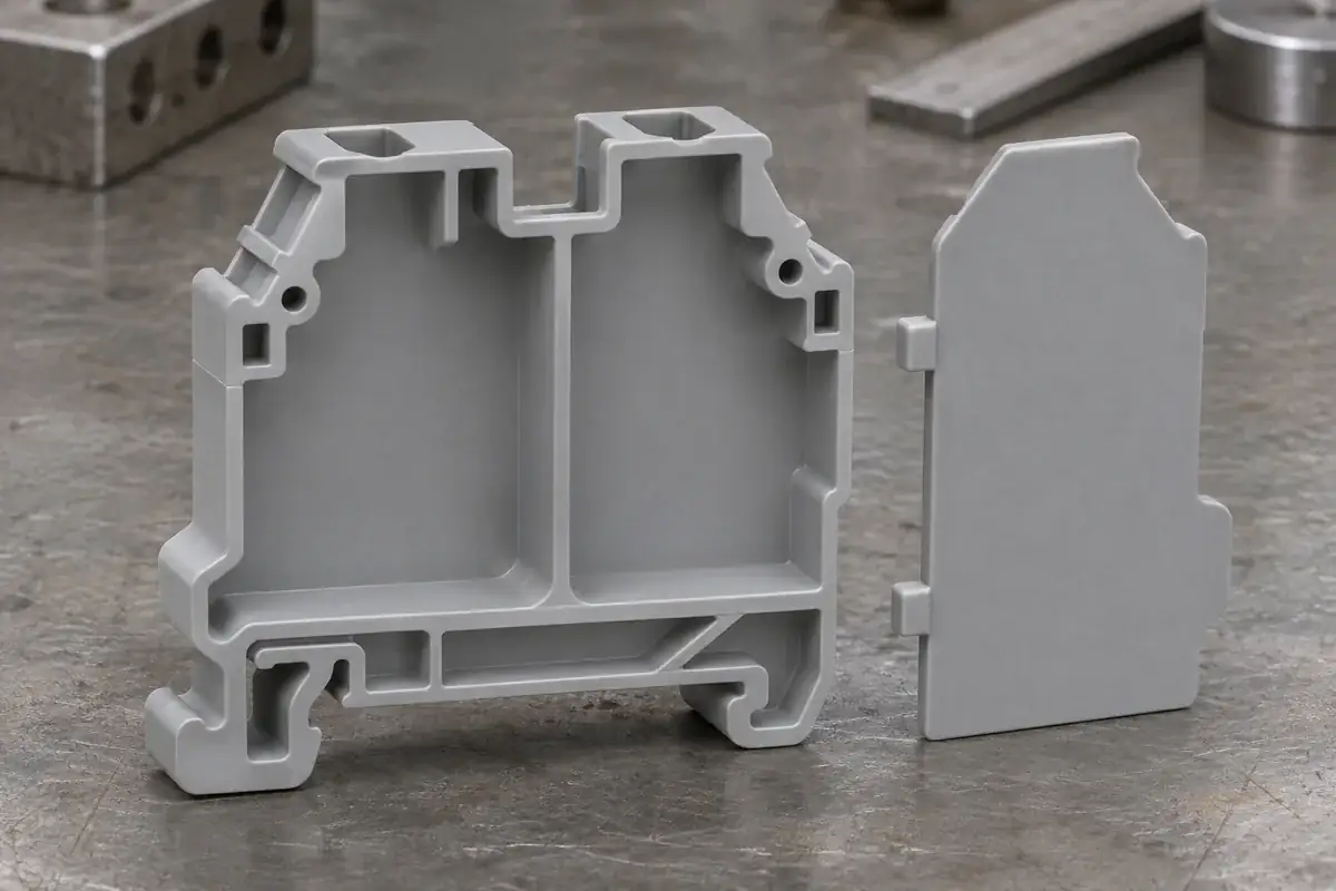
Partitions and end plates
Product design illustration: review the shell and end plate together so the intended separation and attachment features remain continuous.
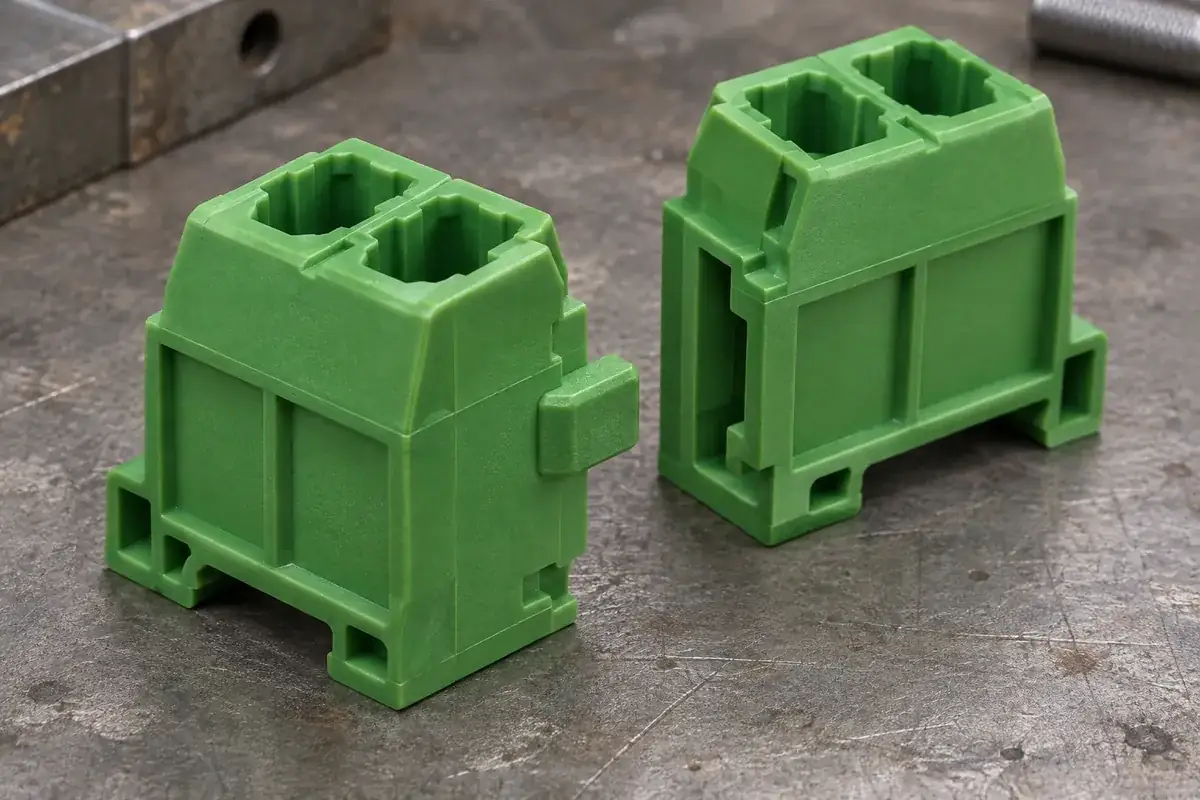
Modular joining features
Product design illustration: control the joining interface and accumulated position across the proposed modular arrangement.
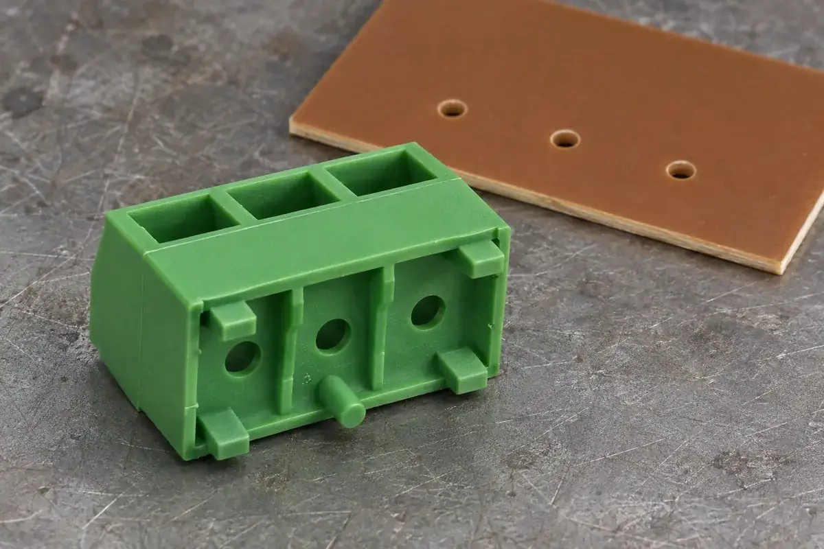
PCB seating references
Product design illustration: relate the housing seating feet and locating features to the board and terminal arrangement.
Illustrative configurations. Final specifications follow your approved drawings.
Application fit
Custom molded components for your terminal block construction
A terminal block housing has to accommodate the metal connection mechanism, the prepared conductor and the surrounding equipment. The molding review starts with that assembly definition. Different connection and mounting arrangements place different demands on the plastic component, even when their nominal pitch is the same.
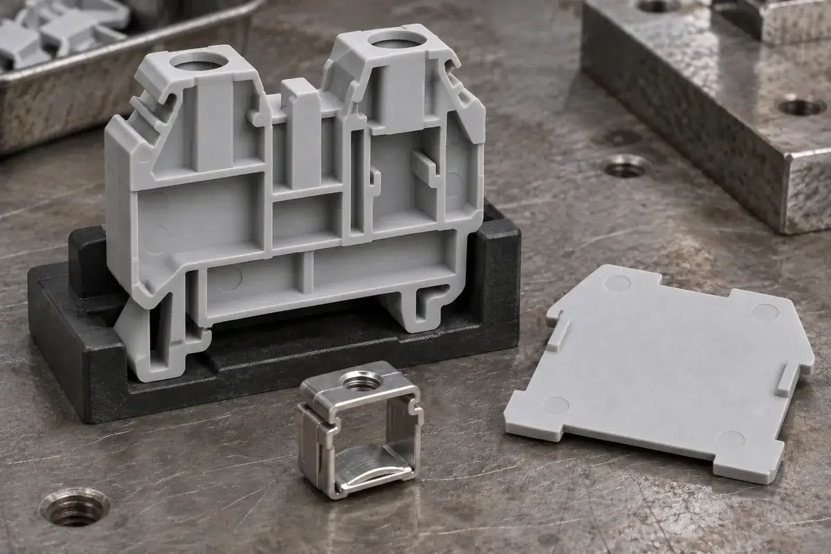
PCB terminal block housings
Insulating bodies with defined terminal passages, conductor-entry features and board seating references. Review the housing together with the terminal drawing and board layout so the plastic feet, locating pegs and operating-tool path suit the actual assembly. Include the soldering process when selecting the resin and establishing the required sample condition.
Rail-mounted housing components
Molded shells and associated insulating pieces for a customer-defined rail-mounted terminal block. Share the rail interface, clamp mechanism and neighboring parts so the installation and removal movements can be reviewed. A rail foot, flexible retention feature and enclosure wall perform different functions and should have separate drawing controls where necessary.
Modular terminal block segments
Plastic segments that join into the proposed pole arrangement. Review the side interface, pitch accumulation, end treatment and assembly support across the intended configurations. Include both the shortest and longest arrangements: a segment that fits individually may expose alignment or access problems when several are installed together.
End plates, partitions and covers
Associated molded components that complete an insulating boundary or protect a defined area of the assembly. Specify their locating surfaces, attachment method and relationship to the live-part envelope. Review any marking recess, tool opening or service access alongside the separation geometry rather than treating these details as cosmetic additions.
Quote-ready inputs
What to send for a meaningful quotation
Use the same drawing and requirements for every proposal. Mark open decisions explicitly so that a low price does not conceal a different deliverable.
| Area | Please provide | Review before release |
|---|---|---|
| Housing and clamp definition | Housing CAD, drawing revision, clamp mechanism drawings and the intended installation sequence. | Identify locating seats, hardware retention, supporting ribs and the surfaces that carry assembly or operating loads. |
| Conductor preparation and entry | Conductor range, insulation dimensions, strip length and any ferrule or other preparation requirements. | Review the prepared conductor envelope through the entry path, including adjacent positions and the available wiring space. |
| Actuation and service access | Operating-tool geometry or actuator definition, approach direction and equipment-space constraints. | Check access in the installed configuration, with neighboring terminals, covers and conductors represented. |
| Insulation and material requirements | Selected resin grade and color, intended exposure, required material documentation and assembly qualification criteria. | Preserve the specified separation geometry and evaluate the material at the relevant wall thickness and processing conditions. |
| Mounting and product family | PCB or rail interface, pole-count variants, end plates, anticipated quantities and tool ownership requirements. | Define the component variants, shared interfaces and any interchangeable tooling features before estimating the manufacturing scope. |
| Sample and inspection evidence | Critical dimensions, datums, assembly reference parts, sample condition and required reporting format. | Agree which molded features and assembly interfaces will be checked, how samples will be identified and who approves release. |
From drawing to approval
Develop the housing around the connection mechanism
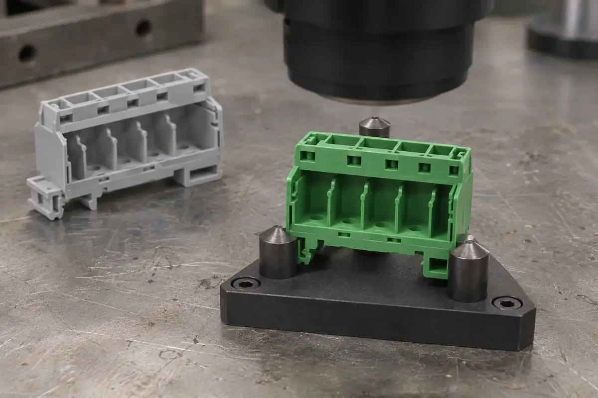
Establish the complete interface set
Review the housing, clamp mechanism, prepared conductor and mounting arrangement together. Identify the hardware seats, conductor stop, operating access and insulating partitions. Record which interfaces are fixed and which can change during development; this makes it possible to evaluate molding proposals against the actual electrical assembly.
Review the tool and material approach
Assess the proposed resin, wall transitions, core access, gate location and parting-line placement. Relate the tooling choices to clamp pockets, small conductor openings, joining features and visible operating surfaces. Resolve features that require a separate component or a more complex mold action before agreeing the tool configuration.
Evaluate molded and assembled samples
Inspect the agreed molded dimensions from functional references, then review identified samples with the intended hardware and installation components. Include the relevant conductor preparation, tool approach and pole-count variants. Record the configuration used for each check so a housing measurement and an assembly observation remain traceable to the same drawing state.
Release the component supply definition
Confirm the drawings, material, tooling state, packaging and component inspection plan. Identify the approved reference hardware and which end plates or other molded accessories are included. Changes to the clamp mechanism, mounting interface or resin can then be reviewed against a clear baseline before subsequent production.
Practical engineering and buying guides
Decisions to make before production
- Screw, Spring or Push-In? Terminal Block Housing DesignCompare terminal-block housing requirements for screw, spring and push-in connections, including clamp support, wire guidance and operating access.
- Terminal Block Wire Entry: Why a Ferrule Fits but Will Not ClampTrace terminal-block wire-entry problems through insulation diameter, ferrule shape, strip length and clamp depth before changing the plastic housing.
- Terminal Block Tool Access: Driver Paths and Insulating GuardsCoordinate terminal-block screwdriver paths, shaft clearance, operating angles and insulating guard walls within the actual equipment installation.
- Terminal Block Housing Cracks: Trace the Tightening Load PathInvestigate terminal-block housing cracks by following screw forces through metal cages, plastic supports and mounting points before changing resin.
- Anti-Rotation Features for Terminal Block Metal InsertsDesign terminal-block insert location around broad flats, support surfaces, assembly clearance and operating forces so metal parts retain their orientation.
- Terminal Block End Plates: Closing the Insulation BoundaryUnderstand when a terminal block row needs an end plate, how it differs from a rail clamp, and which molded interfaces deserve review before tooling.
- Modular Terminal Block Alignment and Pitch Stack-UpLearn why a long modular terminal block row can drift even when individual housings pass inspection, and how to review pitch, joining fit and mounting.
- Pluggable Terminal Block Coding and Circuit IdentificationPlan mechanical coding and readable circuit identification for pluggable terminal blocks, including wrong-pair checks, assembly sequence and service changes.
- PCB Terminal Block Cleaning: Drainage and Drying by DesignReview terminal block standoffs, underside cavities and board clearance for cleaning and drying, while keeping resin compatibility and process validation explicit.
- Terminal Block Barriers, Creepage, Clearance and CTIUnderstand how terminal block barriers affect air and surface paths, what CTI describes, and which assembly details must be reviewed before assigning ratings.
Related connector manufacturing scopes
Explore empty insulating bodies, components molded around metal terminals and the precision mold inserts used to form them. Each scope has its own drawings and acceptance requirements.
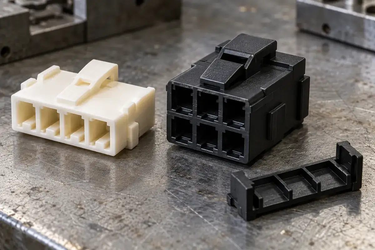
Custom Wire-to-Board Connector Housings
Custom injection-molded wire-to-board connector housings. Review crimp-terminal fit, wire entry, latches, keying and tooling for your plastic components.
Review the application →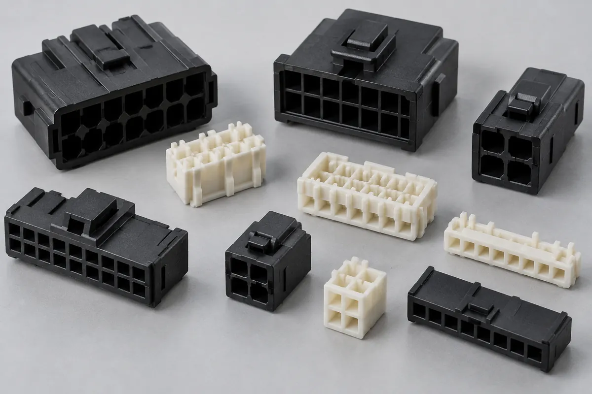
Connector Insulators & Terminal Carriers
Custom molded insulating bodies and terminal carriers. Define terminal interfaces, locating references, exact resin and component acceptance.
Review the application →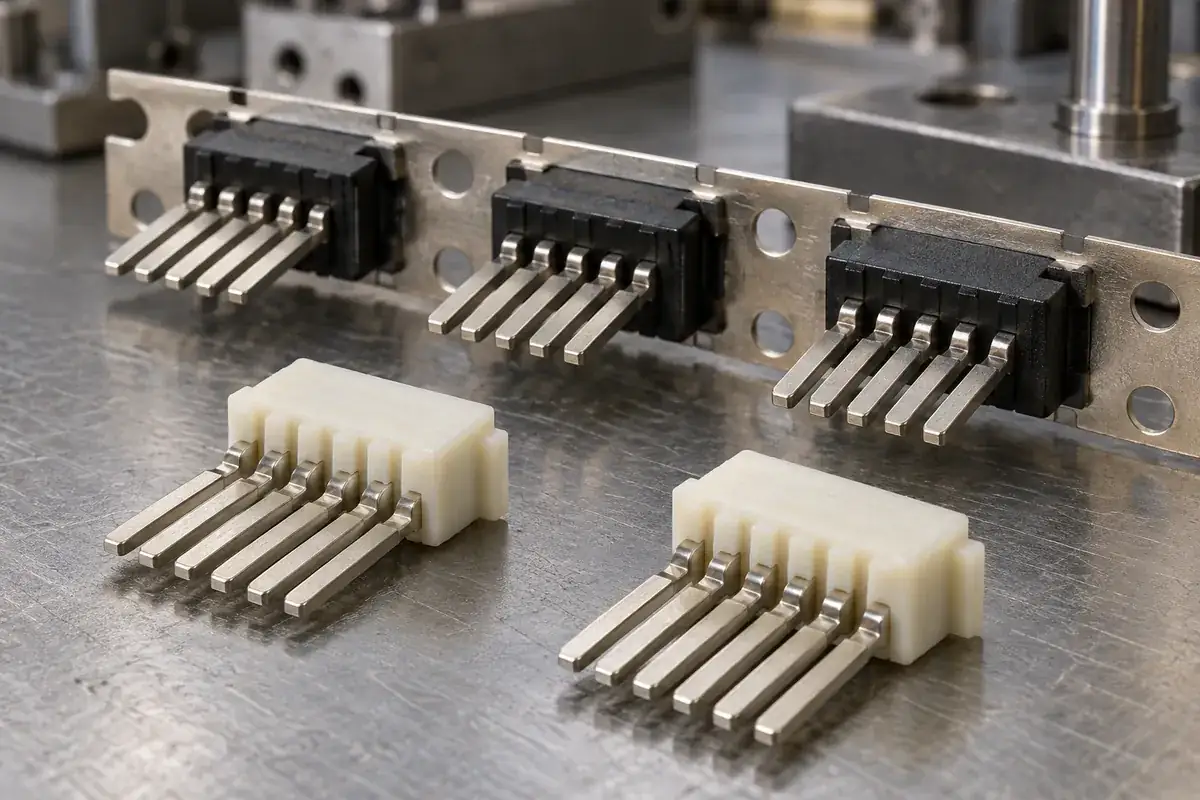
Custom Insert-Molded Connector Components
Custom connector components combining stamped terminals and molded plastic. Review contact location, carrier strips, resin shutoffs, tooling and inspection with FECISION.
Review the application →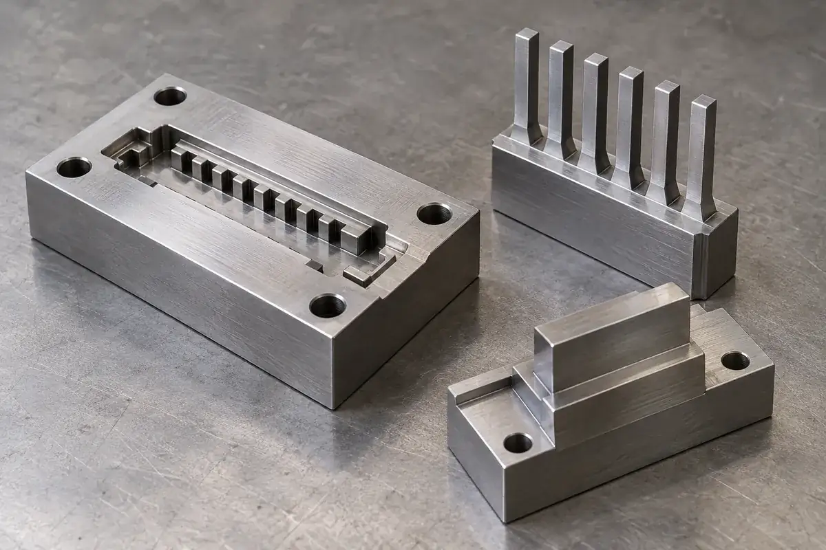
Precision Connector Mold Inserts
Custom steel mold inserts for connector tooling: cavity inserts, thin cores and comb features. Review drawings, locating fits, finishing and replacement scope with FECISION.
Review the application →Before you request a quote
What information is needed to quote a custom terminal block housing?
Send the housing CAD and drawing, the connection hardware definition and the intended conductor and mounting requirements. Include resin and color requirements, pole-count variants, end plates, quantities and the inspection evidence you need. Showing how the parts are assembled helps define the tooling and sample review accurately.
Can the same plastic housing support screw and spring-clamp connections?
That depends on the proposed mechanisms and their interfaces. Their support surfaces, actuation movement, conductor entry and loading sequence can differ substantially. Provide the specific hardware drawings for each version so shared features and separate housing requirements can be assessed.
How are electrical ratings and approvals handled?
Provide the target ratings, applicable requirements and the planned completed-assembly qualification. Housing material data, wall thickness, separation geometry and dimensional evidence support that work. The terminal block configuration, including its metal hardware and intended conductors, defines the assembly that must be evaluated.
Which resin should be used for the insulating body?
Use the specified grade where the design already has an approved material. For a new design, supply the thermal exposure, mechanical demands, insulation requirements, color and required declarations so candidate grades can be screened. A broad polymer name or a flammability classification alone does not settle every housing requirement.
Can you review both PCB and rail-mounted housing designs?
Yes. Share the proposed component drawings and installation definition for review. A PCB housing requires attention to board seating, terminal alignment and the intended soldering exposure; a rail-mounted construction also needs its installation, retention and release geometry assessed. The component and tooling scope is defined for the actual design.
Can different pole counts share a tooling approach?
Potentially. Modular joining, interchangeable tool details and separately tooled lengths involve different dimensional, assembly and cost trade-offs. Supply the intended lengths, demand split and end-treatment requirements so the alternatives can be reviewed against the family rather than a single part.
What should be checked when approving housing samples?
Agree the critical features and assembly checks before sampling. These may include clamp-seat position, conductor-entry geometry, tool access, partitions, mounting references and modular joining. Use identified hardware and reference components for assembly checks, and define the measurement condition, acceptance criteria and reporting responsibilities.
Your next step
Discuss the part with its intended function.
Send the housing model, clamp mechanism and installation details. We will review the molded interfaces and prepare a tooling, sample and production quotation for your terminal block component program.
Explore our connector injection molding service or review other connector components and mold inserts.