
Precision connector components · Made to your design
Custom Wire-to-Board Connector Housings
Build the wire-side housing around the terminal, the finished crimp and the way the harness is assembled.
FECISION reviews custom injection-molded plastic housings for wire-to-board connector programs. Share the housing model, terminal drawing and mating-header definition together so terminal entry, locking shoulders, polarization and wire routing can be assessed before tooling. We coordinate mold development, sample molding and the agreed component inspection around the interfaces your assembly needs to preserve.
Product details
Explore the plastic features that guide the wire-side assembly
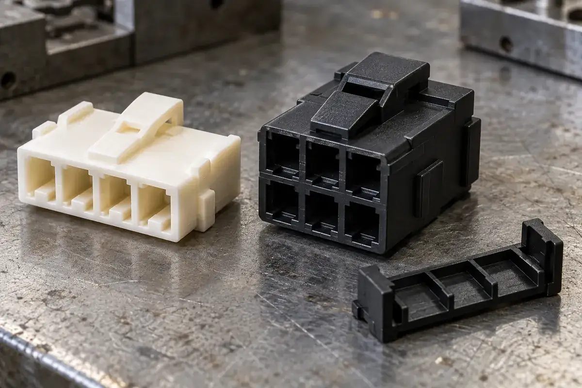
These product design illustrations show empty terminal cavities, latch structures, side keys and rear wire guides. Each feature is reviewed against the terminal and counterpart drawings for the proposed housing.
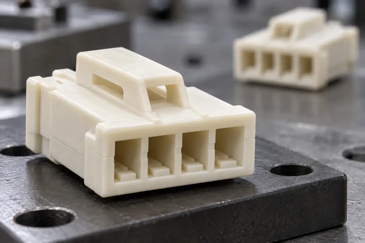
Terminal cavity geometry
Product design illustration: connect terminal entry, locating shoulders and the mating face in one cavity definition.
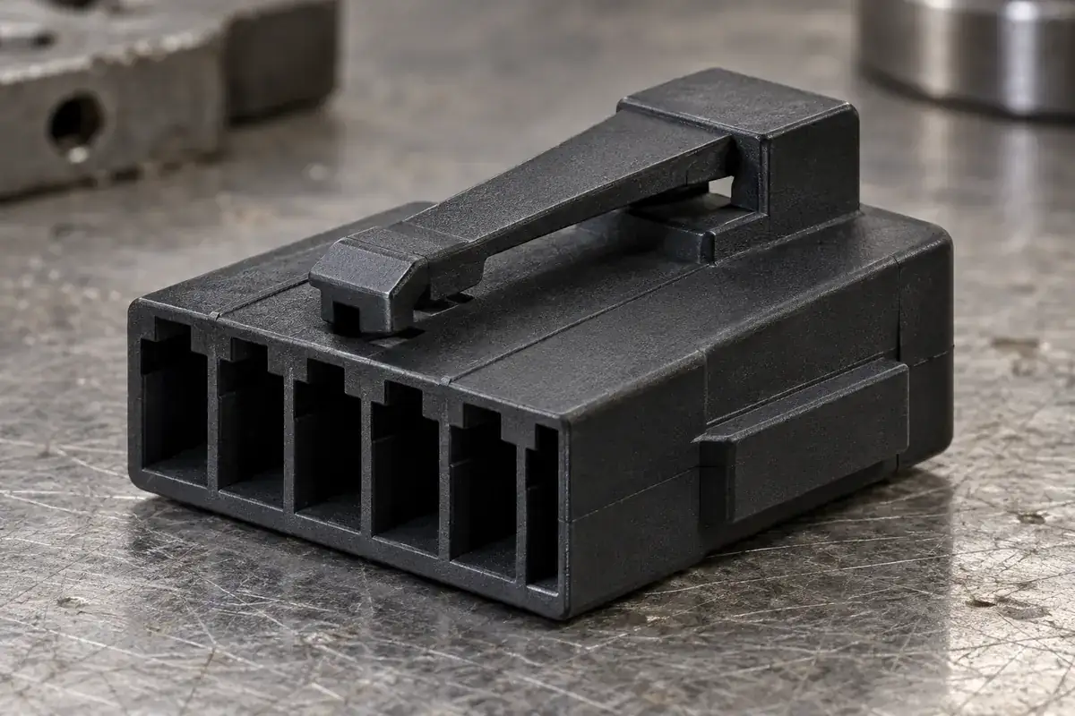
Latch and release access
Product design illustration: review the latch engagement surface and the space needed to release it in the installed assembly.
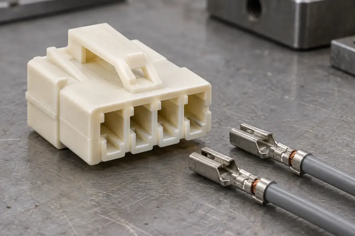
Finished crimp interface
Product design illustration: compare the completed terminal-and-wire envelope with the entry path, rather than checking the bare terminal alone.
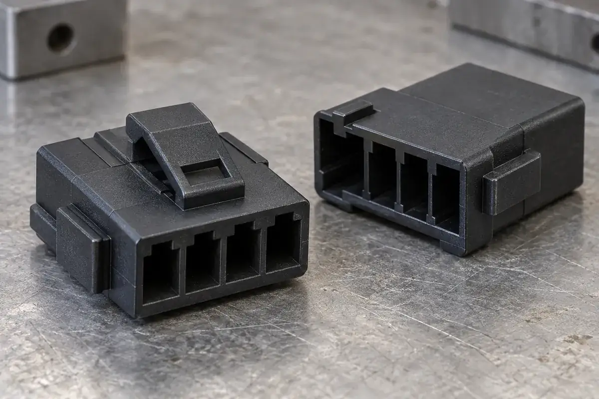
Physical keying
Product design illustration: specify the key positions and guide surfaces that distinguish the intended mating configuration.
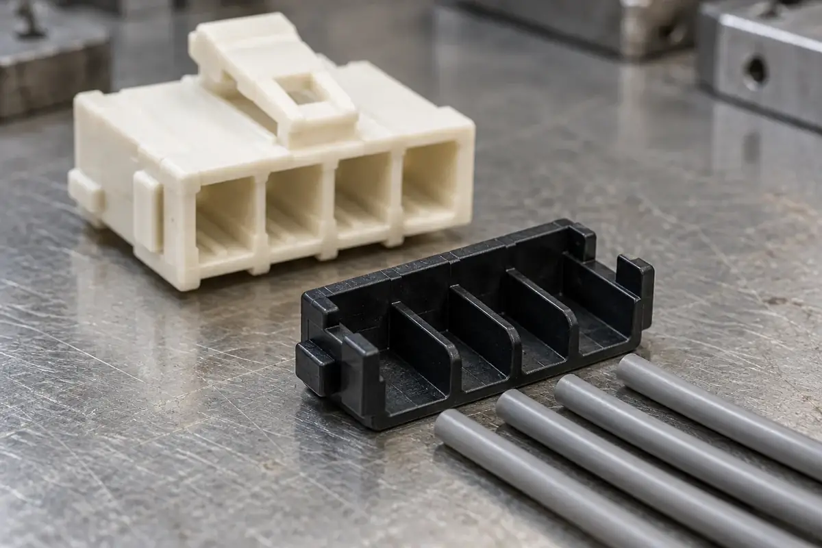
Rear wire organization
Product design illustration: define wire routing and cover clearance together with any separately required strain-relief function.
Illustrative configurations. Final specifications follow your approved drawings.
Application fit
Wire-side plastic components for your connector design
The housing is molded empty and receives prepared terminals during a later assembly operation. Its geometry must accommodate that sequence as well as the final connection. We review the plastic component and its related molded accessories against a customer-defined design.
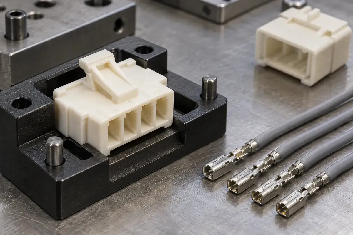
Single-row crimp housings
Molded bodies with a defined row of terminal cavities, a mating envelope and the required retaining features. Review the completed crimp profile at the wire entry, the terminal orientation and the accessible path for insertion or service removal. A simple exterior can contain several different functional surfaces that need separate drawing control.
Multi-row wire-side housings
Compact arrangements where adjacent terminals and wires share limited assembly space. Review the loading order, access to the inner cavities and the route of each wire after installation. The selected cavity pattern should remain practical to populate and inspect, not merely fit within the available package.
Keyed housings and latch features
Customer-defined side keys, guide ribs and locking structures that coordinate the wire-side housing with its counterpart. Include the installed operating space, intended mating direction and release action. Physical keying, visual identification and terminal orientation each address a different assembly decision.
Rear covers and wire guides
Associated molded pieces for organizing wires and protecting the area behind the terminal cavities. Review the insulation outside diameter, completed crimp length, cover attachment and expected wire route. Where strain relief is required, define how the load is transferred into the housing or an external support.
Quote-ready inputs
What to send for a meaningful quotation
Use the same drawing and requirements for every proposal. Mark open decisions explicitly so that a low price does not conceal a different deliverable.
| Area | Please provide | Review before release |
|---|---|---|
| Housing and counterpart | Housing CAD, drawing revision, mating-header geometry and the installed-space envelope. | Identify cavity datums, mating stops, key positions and the features that must remain unchanged during tooling development. |
| Terminal and completed crimp | Terminal drawing, wire range, insulation outside diameter and the approved crimp configuration. | Review the entire insertion envelope, locking interface and extraction path using the delivered terminal-and-wire condition. |
| Wire routing and accessories | Loading order, partially populated variants, rear cover, wire guide and harness support arrangement. | Resolve space for adjacent wires, cover closure, unused positions and access to the release features. |
| Material and exposure | Exact resin grade if selected, color, required declarations and actual thermal, chemical or handling conditions. | Assess the molded latch and cavity geometry against the chosen grade and assembly exposure. Keep the housing and header process requirements distinct. |
| Tooling and quantities | Development quantity, recurring demand, variant strategy and any existing tool information. | Define the cavity concept, interchangeable details where appropriate, sample approval stages and manufacturing-change responsibilities. |
| Inspection and release | Critical features, reference parts, measurement condition, sample identification and reporting format. | Agree how dimensional evidence and relevant assembly checks will be recorded for the approved housing configuration. |
From drawing to approval
Connect component definition to harness assembly
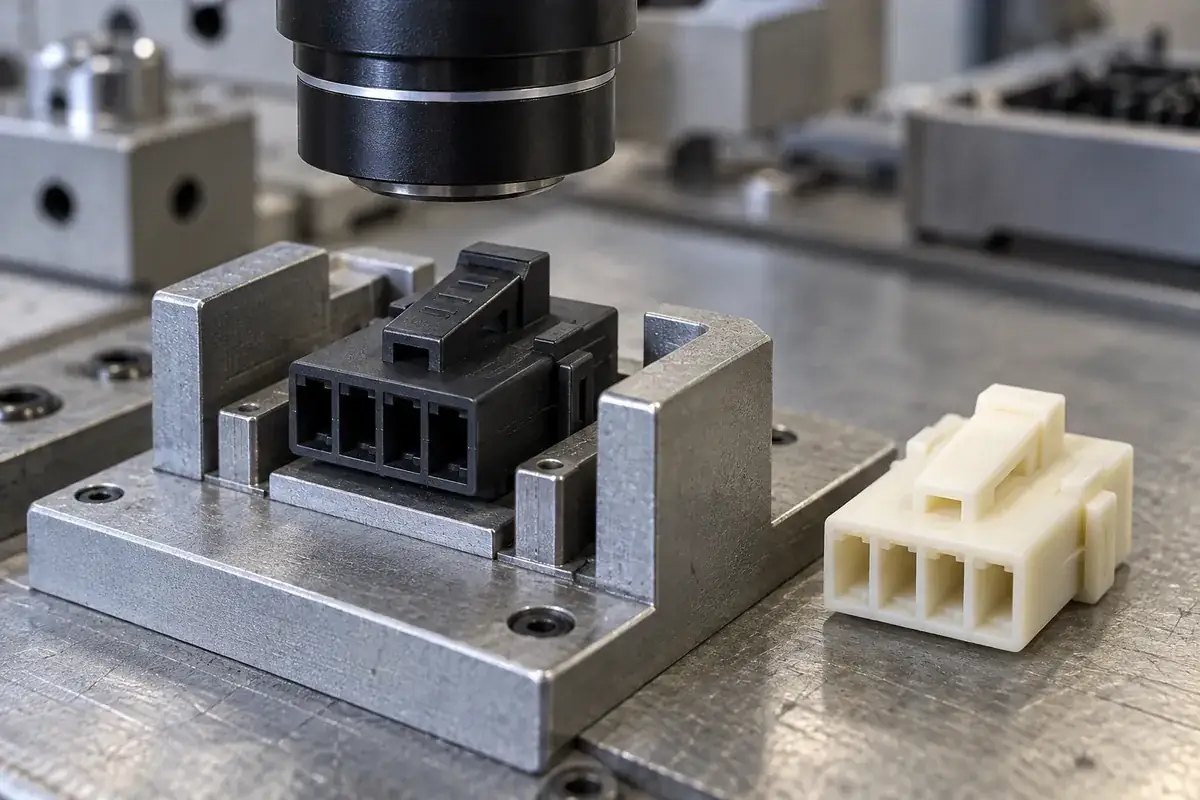
Map the interfaces before tooling
Review the housing, finished crimped terminal and mating header together. Establish the insertion direction, terminal stop and retaining interface. Include the wire exit, surrounding enclosure and any rear accessory so a convenient molding change does not obstruct the downstream assembly.
Develop the molding approach
Evaluate the material, core features, mold opening directions and the surfaces requiring particular control. Relate gate and parting-line choices to terminal entry and mating features. Review any proposed geometry changes against the original assembly intent before committing them to the tool.
Evaluate identified trial parts
Measure the agreed molded features and use the specified terminals and counterparts for the relevant assembly review. Include intended wire sizes and population variants. An empty shell check and a fully loaded harness check answer different questions, so record the configuration used for each result.
Release a defined supply configuration
Confirm the housing drawing, resin, color, tooling state, packaging and approved inspection plan. Specify whether the delivery consists of empty housings alone or includes additional molded accessories. Changes to terminals, wire insulation or counterpart revisions can then be assessed against the accepted interfaces.
Practical engineering and buying guides
Decisions to make before production
- Wire-to-Board Connector Types: Choosing the HousingCompare wire-to-board housing types through termination, mating access, locking and harness routing before defining a custom molded component.
- Wire Gauge vs Insulation Diameter in Connector HousingsUnderstand why equal-AWG wires can fit connector housings differently. Review insulation diameter, crimp envelopes and rear-entry geometry together.
- Why a Crimp Terminal Will Not Enter Its HousingTrace crimp-terminal insertion interference through orientation, formed crimp wings, contact straightness and housing entry geometry before changing tooling.
- Terminal Orientation and Keying in Wire-to-Board HousingsSeparate terminal orientation, cavity numbering and mating polarization. Design wire-to-board housing guides around the actual contact loading sequence.
- Wire-to-Board Harness Exit and Bend SpacePlan wire-to-board harness exits around free wire length, bend direction, support points and latch access so routing loads do not concentrate at the connector.
- Terminal Extraction Access for Wire-to-Board HousingsReview the release window, extraction tool path and wire access of a wire-to-board housing before a repair turns into a damaged contact or locking feature.
- Unused Connector Cavities: Leave Open, Block or Seal?Plan partially populated wire-to-board housings by separating circuit selection, assembly blocking and sealing, including cavity-plug fit and service access.
- Friction Lock or Positive Latch for a Wire-to-Board Housing?Compare friction retention and positive latching through harness loads, operating access and service needs before choosing a custom wire-to-board housing interface.
- Loading a Multi-Wire Housing Without Blocking the Next TerminalPlan wire-to-board terminal loading around changing cavity access, wire routing and confirmation steps so a populated harness remains practical to assemble.
- Wire-to-Board Rear Covers: Routing and Crimp ClearanceReview wire exits, crimp clearance, closure paths and load transfer when designing rear covers for custom wire-to-board connector housings.
Related connector manufacturing scopes
Explore empty insulating bodies, components molded around metal terminals and the precision mold inserts used to form them. Each scope has its own drawings and acceptance requirements.
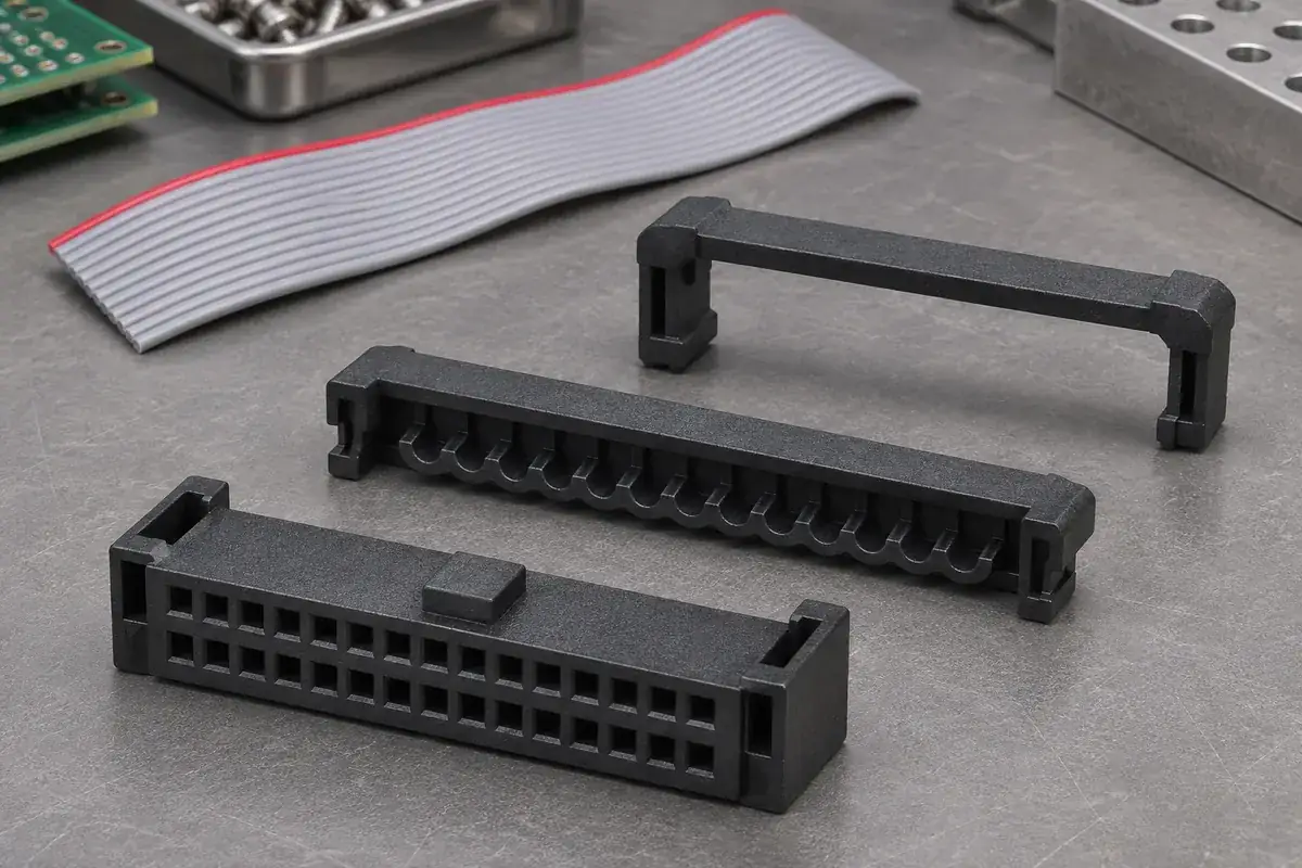
Custom IDC Connector Housings and Covers
Custom molded IDC connector housings, pressure covers and strain-relief parts. Review ribbon-cable location, latch travel, tooling and assembly requirements.
Review the application →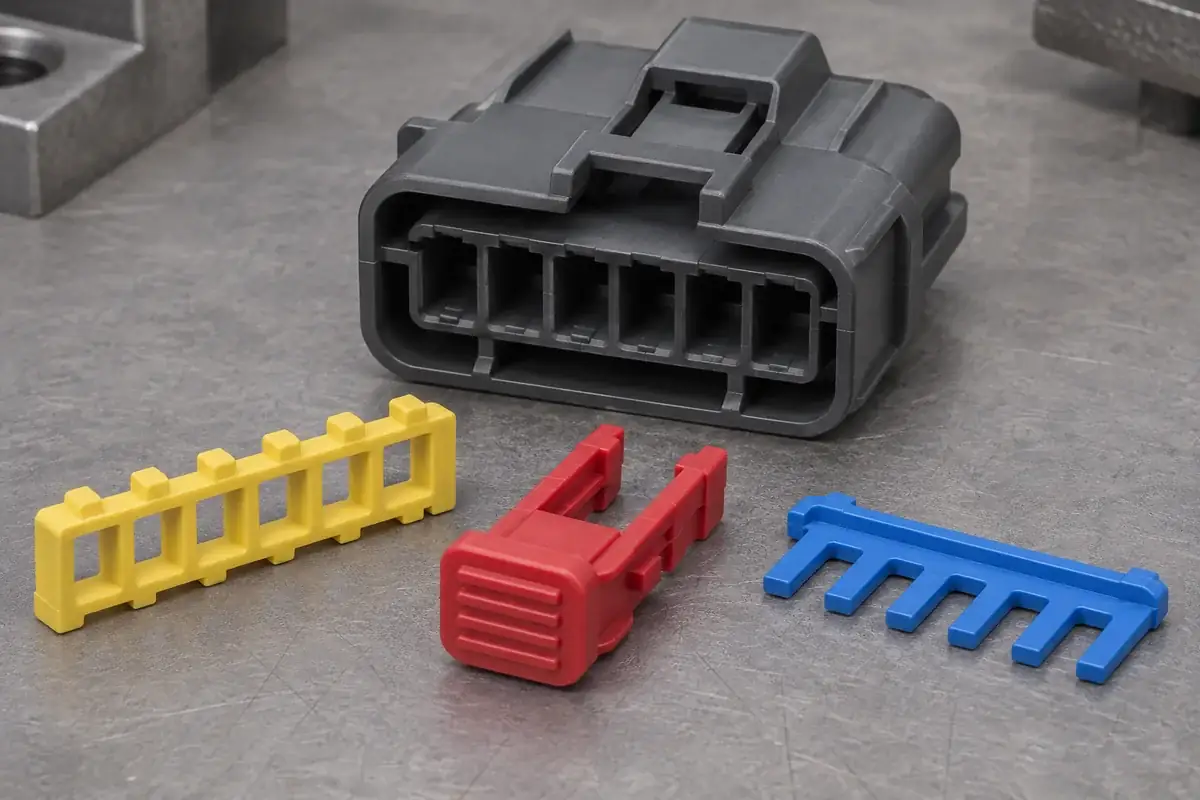
Custom TPA and CPA Connector Secondary Locks
Custom injection-molded TPA and CPA connector locks made to your drawing. Review retaining shoulders, guide rails, detents, assembly access and inspection.
Review the application →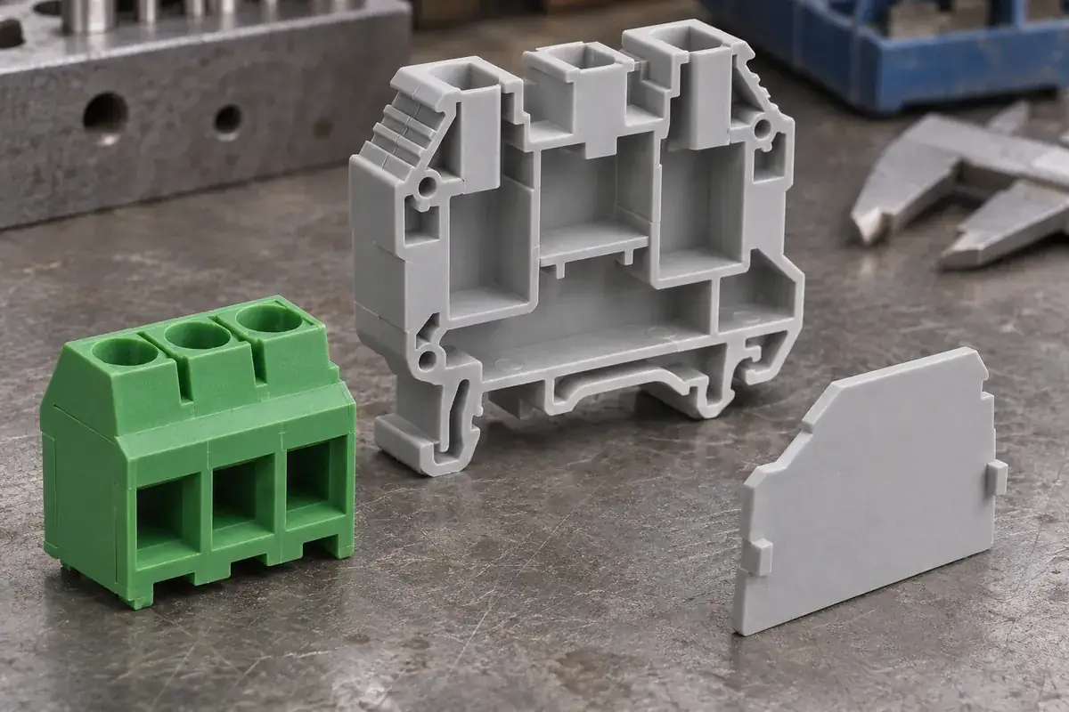
Custom Terminal Block Housings
Custom injection-molded terminal block housings, insulating partitions and end plates. Review clamp seats, conductor entry, tool access and mounting geometry.
Review the application →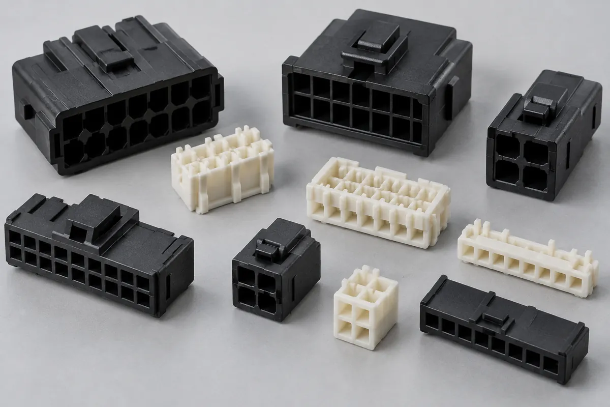
Connector Insulators & Terminal Carriers
Custom molded insulating bodies and terminal carriers. Define terminal interfaces, locating references, exact resin and component acceptance.
Review the application →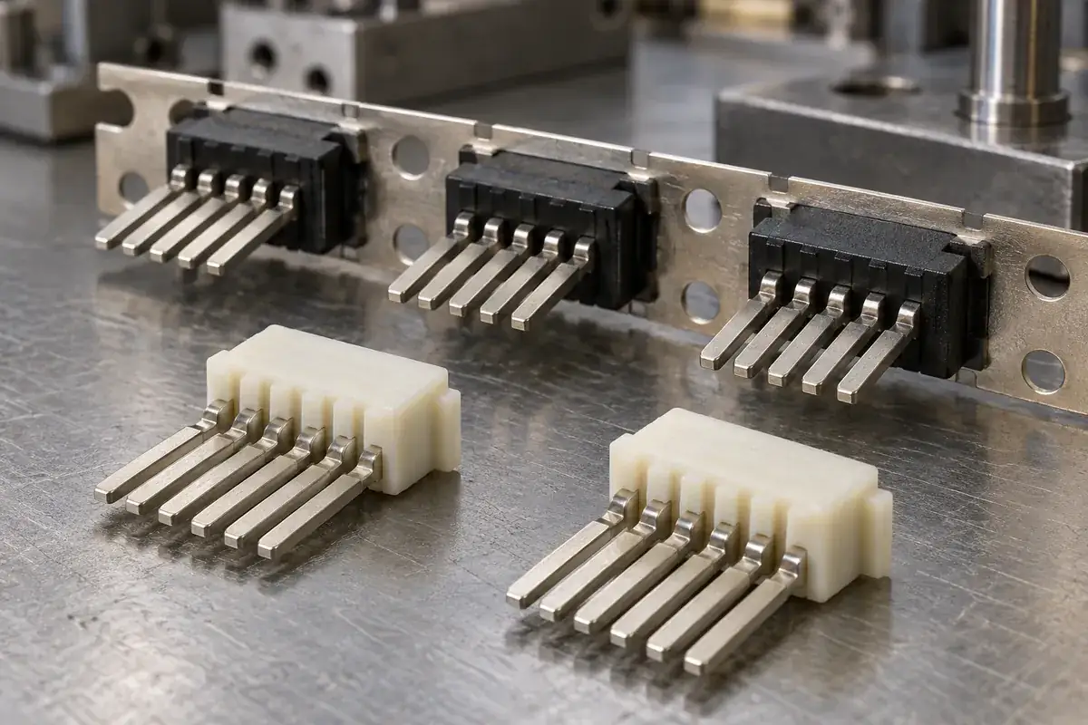
Custom Insert-Molded Connector Components
Custom connector components combining stamped terminals and molded plastic. Review contact location, carrier strips, resin shutoffs, tooling and inspection with FECISION.
Review the application →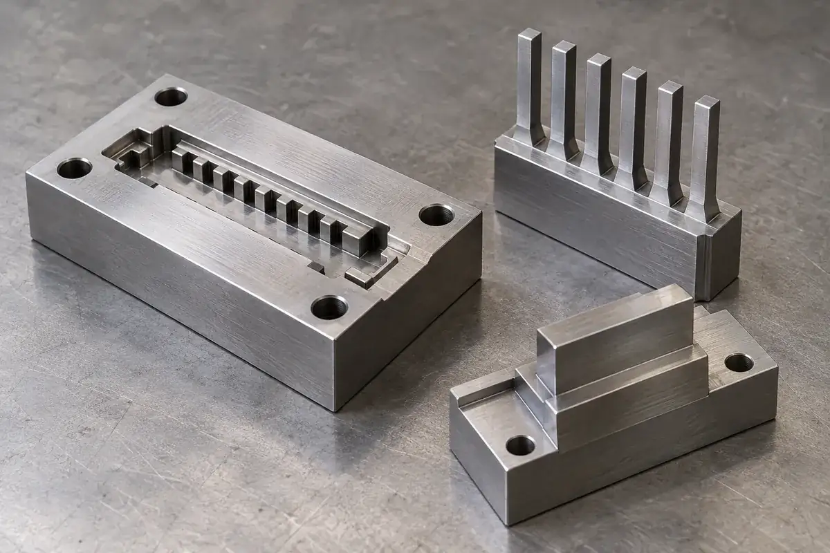
Precision Connector Mold Inserts
Custom steel mold inserts for connector tooling: cavity inserts, thin cores and comb features. Review drawings, locating fits, finishing and replacement scope with FECISION.
Review the application →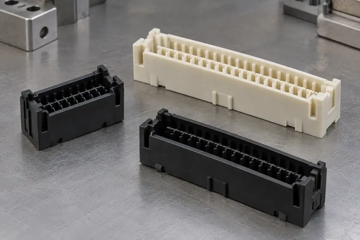
Custom Board-to-Board Connector Housings
Custom molded board-to-board connector housings. Review stack height, alignment, contact cavities, mounting features and inspection with FECISION.
Review the application →Before you request a quote
What should I send for a wire-to-board housing quotation?
Send the housing CAD and drawing, the terminal and mating-header definitions, the intended wires and completed crimp information. Add material requirements, quantities, rear accessories, installation-space constraints and the inspection evidence you need. This allows the quote to address the actual component and its assembly interfaces.
Is this the same process as molding plastic around metal terminals?
This page focuses on empty plastic housings that receive prepared terminals after molding. Insert-molded connector components are a different construction in which metal is located in the mold before injection. We can review that route through the dedicated insert-molded connector component program.
Can one housing accommodate different wire sizes?
Possibly, when the terminal system and housing geometry support the intended combinations. Conductor size alone is insufficient: insulation diameter, completed crimp shape, adjacent-wire space and any rear accessory also matter. Supply each proposed combination for review.
Can you include a latch, physical key or rear wire guide?
These features can be included in the drawing review. Share the counterpart, operating space and assembly sequence so the feature can be assessed in use. A rear guide organizes the wire path; any required strain-relief duty should have its own defined load path and acceptance requirements.
Which resin should the housing use?
Candidate grades depend on the terminal arrangement, latch behavior, exposure, declarations and molding requirements. Provide the selected grade or the application requirements for screening. The wire-side housing may experience different processing from the PCB-mounted header, so their material decisions should be reviewed separately.
Can the housing be used with an existing connector family?
Provide the controlled counterpart drawings and the required interface definition for review. Similar appearance or the same nominal pitch does not establish interchangeability. Approval should use the intended terminals, counterpart and assembly conditions.
What can be checked during sample approval?
The plan can cover specified cavity dimensions, terminal location, key and latch geometry, and agreed assembly checks with identified reference components. Define the sample condition and pass criteria in advance. Electrical ratings and environmental qualification are assessed for the completed configuration under the applicable project requirements.
Your next step
Discuss the part with its intended function.
Send the housing model with the terminal, wire and mating-header details. We will review the molded interfaces and prepare a tooling, sample and production quotation for your wire-to-board component program.
Explore our connector injection molding service or review other connector components and mold inserts.