
Precision connector components · Made to your design
Custom USB Connector Insulators and Terminal Carriers
Control the plastic tongue and its locating interfaces as one defined component.
FECISION reviews custom molded insulating tongues, terminal carriers and plastic retaining parts for customer-designed USB connector assemblies. Share the plastic model together with the relevant contact and shell geometry. We connect thin-section molding, gate and ejector locations, assembly support and dimensional inspection to the interfaces your component must maintain.
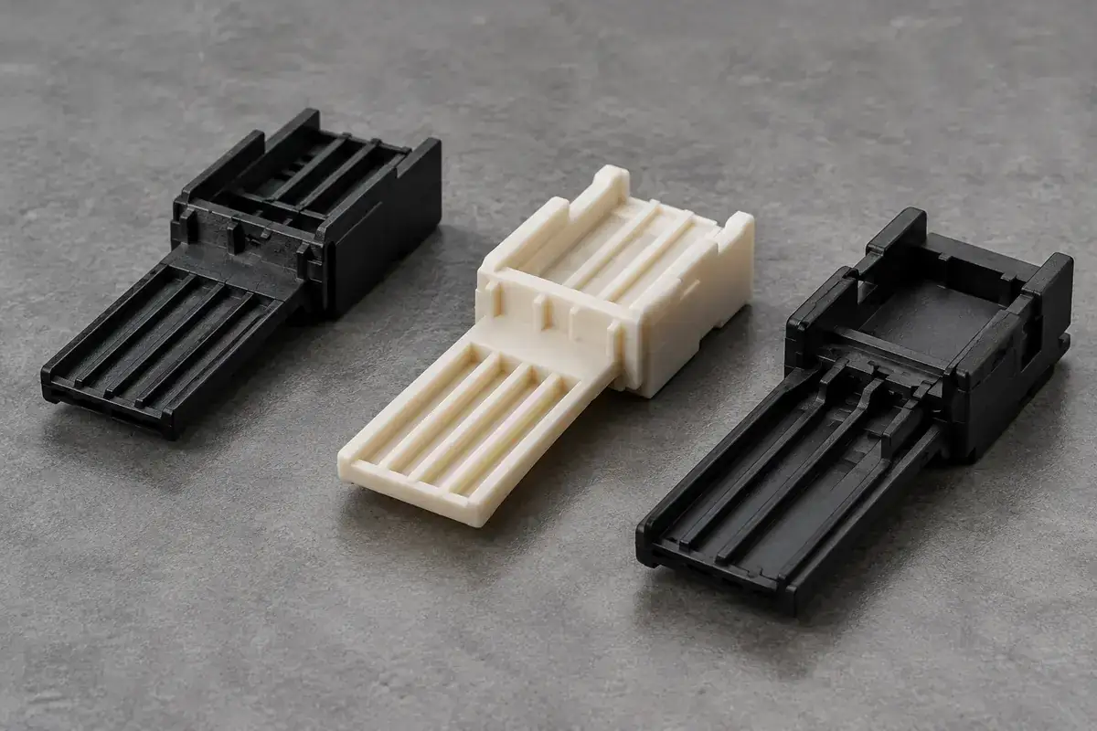
Product details
The molded features behind the connector interface
Product design illustrations show empty plastic components and their relevant interfaces. Each example focuses on a manufacturing decision to review against your approved drawings.
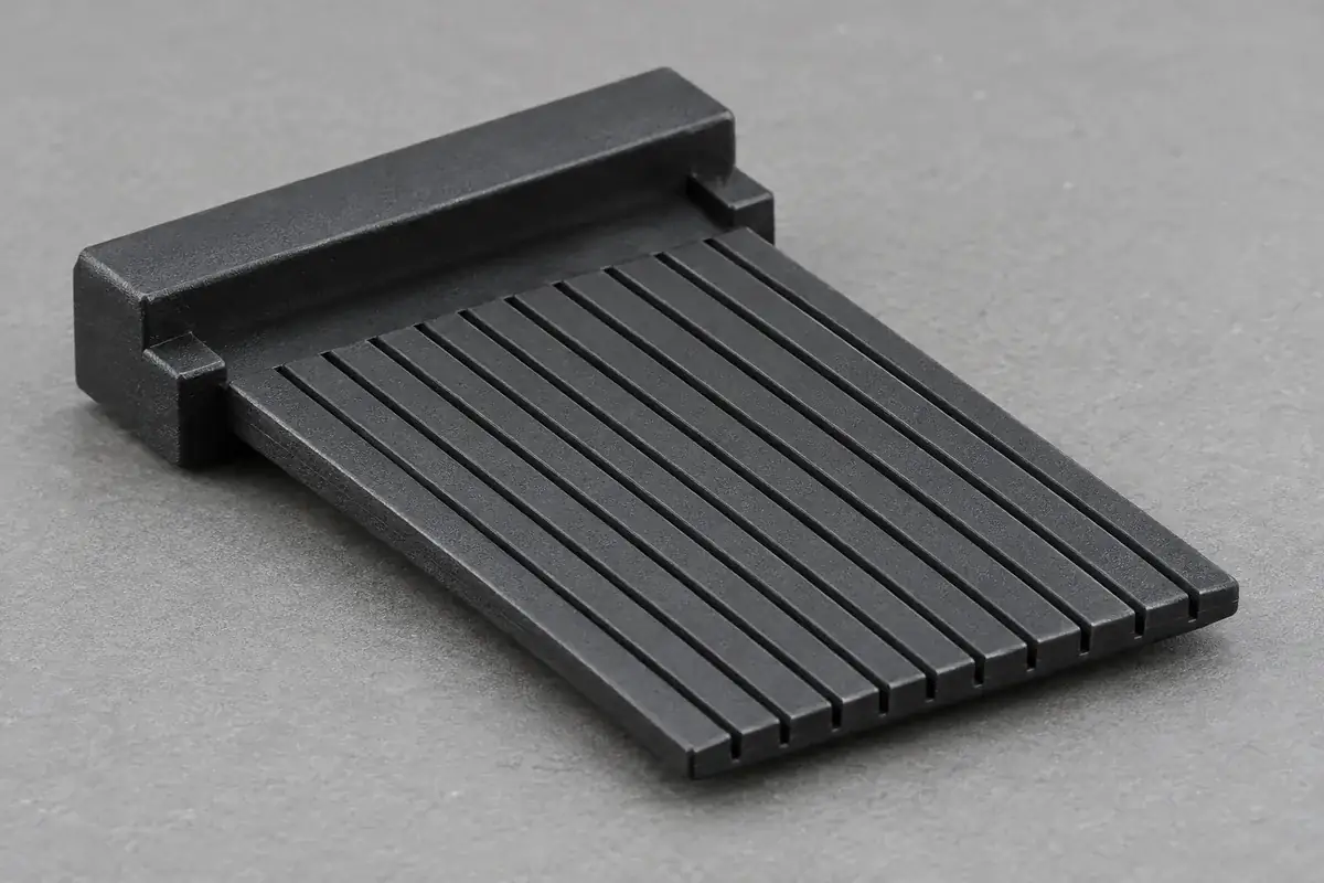
Insulating tongue and contact channels
Product design illustration: review the tongue section, channel entry and separating ribs against the contact installation path.
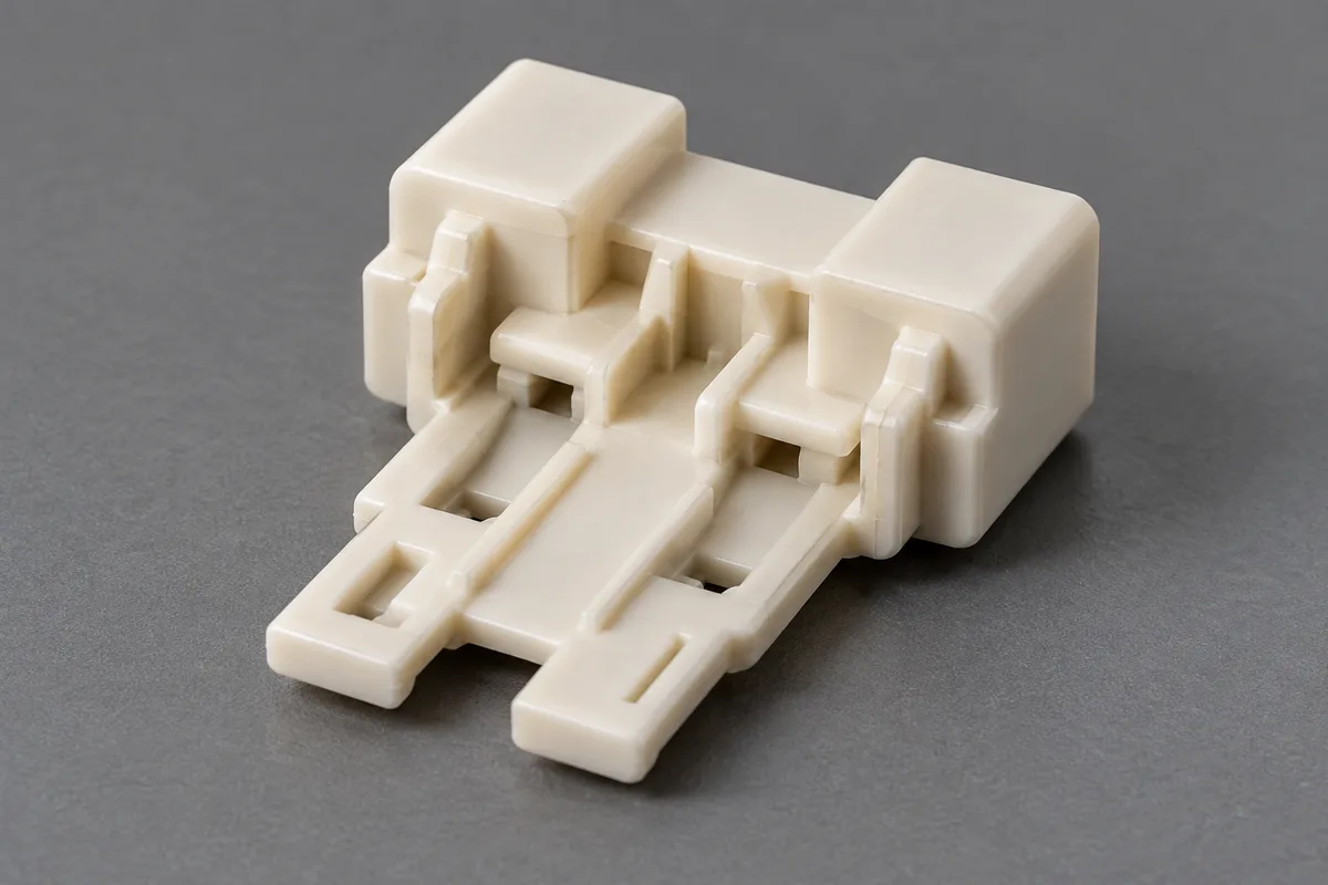
Carrier locating shoulders
Product design illustration: connect the carrier seats to the tongue position and the shell references that locate the part.
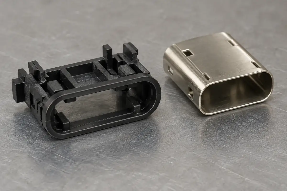
Plastic retaining interfaces
Product design illustration: define where a plastic feature guides, locates or retains the assembly before selecting the molding and inspection approach.
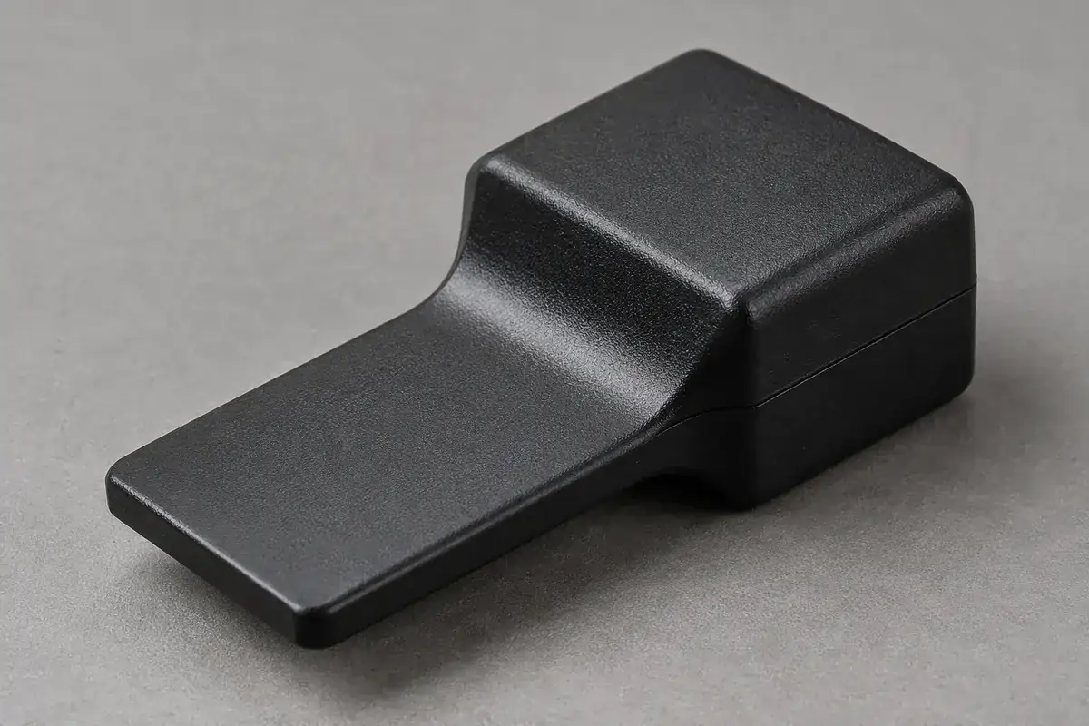
Thin tongue and supported root
Product design illustration: review section transitions, flow direction and support without loading the thin projecting region unnecessarily.
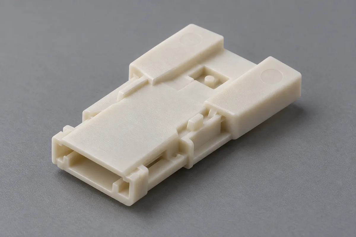
Gate and ejection regions
Product design illustration: place manufacturing witnesses within agreed envelopes while preserving the functional seating and contact surfaces.
Illustrative configurations. Final specifications follow your approved drawings.
Application fit
Custom plastic components for a defined USB assembly
The tongue, rear carrier and retaining pieces perform different jobs. Identifying the delivered item and the surrounding assembly references gives tooling and sample development a practical target. The review follows the plastic component from filling and ejection through its intended installation.
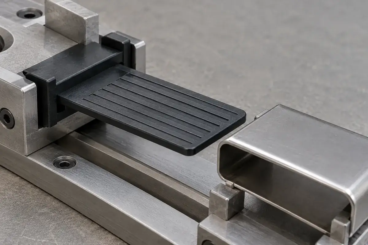
Insulating tongues
Drawing-defined thin projecting bodies with contact-guiding or separating geometry. Review tongue shape relative to the rear locating surfaces, local channels and root transitions. The molding plan should protect the required surface state while providing a workable filling and release route.
Terminal carriers
Plastic carriers that guide or support the customer-defined contact arrangement. Include installation direction, retention regions and the counterpart geometry. Distinguish the dimensions of individual openings from the position of their pattern relative to the shell or receiving subassembly.
Retaining and locating parts
Separately molded plastic pieces that position or retain an insulating component in a specified connector construction. Review lead-ins, engagement regions and the assembly load path together. The quotation identifies the plastic items, secondary operations and inspection deliverables included in the supply.
Quote-ready inputs
What to send for a meaningful quotation
Use the same drawing and requirements for every proposal. Mark open decisions explicitly so that a low price does not conceal a different deliverable.
| Area | Please provide | Review before release |
|---|---|---|
| Plastic geometry and revision | Part CAD, controlled drawing, intended USB assembly context and identification of the delivered plastic items. | Resolve the tongue section, channel geometry, retaining features and surfaces that require design approval before modification. |
| Contacts and shell interfaces | Relevant counterpart drawings, assembly direction, shell seats and stops, contact installation path and support arrangement. | Connect the tongue and carrier datums to the actual assembly references; review the full insertion path as well as the final position. |
| Material and exposure | Exact resin grade where selected, color, reinforcement, documentation and the actual downstream thermal or chemical exposure. | Review grade-specific molding behavior and the evidence needed after relevant exposure. Material data supports selection; component behavior is evaluated in its defined configuration. |
| Tooling and surface restrictions | Permitted gate and ejector zones, parting-line restrictions, contact-path requirements and protected seating surfaces. | Evaluate thin-section filling, weld-line locations, release forces and witness envelopes together rather than treating each surface mark as an isolated cosmetic issue. |
| Inspection and acceptance | Critical features, datums, sample condition, restrained or free-state requirements, cavity identification and report format. | Agree measurement access, support, edge evaluation and any component assembly check. Keep dimensional release and complete-product qualification evidence attached to their respective scopes. |
| Quantity, handling and packing | Trial quantities, recurring demand, part orientation, required incoming condition and packing or traceability requirements. | Define transfer and package contact so thin tongues remain protected and loose material stays away from narrow channels. Confirm commercial quantities after the manufacturing review. |
From drawing to approval
Develop the plastic part around its functional interfaces
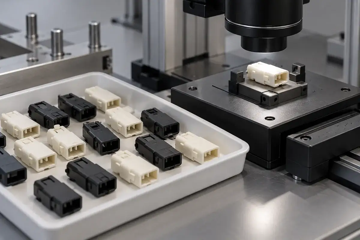
Connect the part to its assembly
Reconcile the plastic, contact and shell revisions. Identify where the carrier seats, how it enters the shell and which regions carry assembly force. Define the item being supplied and the interfaces that must remain fixed while manufacturing details are developed.
Review the molding and release route
Evaluate the selected grade, flow into thin regions, local meeting fronts and the supported root. Coordinate the gate, separation operation and ejection arrangement with the permitted witness regions. Record proposed geometry changes for design review before modifying a functional interface.
Evaluate identified samples
Inspect the agreed features from the functional datums in the specified sample state. Preserve cavity and tooling-configuration identity. Where the scope includes an assembly evaluation, use controlled counterparts and document the support and installation conditions so the observation can be reproduced.
Release the configuration and handling method
Connect approved samples, dimensional evidence, material identification and the drawing revision. Define the recurring checks and changes that require review. Confirm the packing arrangement protects the thin geometry and delivers the required condition to the receiving process.
Practical engineering and buying guides
Decisions to make before production
- USB Connector Insulators vs Complete ConnectorsDefine the molded USB tongue, terminal carrier and retaining parts separately from the complete connector, then connect their drawings to assembly requirements.
- USB Connector Tongue Flatness and Inspection SupportUnderstand how molding flow, root geometry and fixture support affect USB insulating tongue flatness, and separate free-state inspection from assembly checks.
- Controlling Flash in USB Connector Contact SlotsTrace contact-slot flash to the molding interface, distinguish it from short fill and damage, and define inspection around the terminal installation path.
- USB Insulator and Shell Datum Stack-UpConnect tongue position to carrier shoulders, shell stops and inspection datums so a USB plastic component can be evaluated in its intended assembly.
- Gate Vestige Location on USB Connector InsulatorsPlace the gate and its remaining witness around the USB insulator’s flow path, shell seating surfaces and contact channels, with controlled trimming access.
- Ejection Marks on USB Connector InsulatorsControl ejector witnesses and release forces on USB insulating tongues by relating pin locations, support regions and surface acceptance to assembly function.
- Preventing USB Insulator Damage During Shell AssemblyDiagnose scraping, cracking and deformation when a USB insulator enters its shell by reviewing the lead-in, support, insertion path and component evidence.
- Weld Lines in Molded USB Connector TonguesReview weld-line location in a molded USB tongue against its flow path, thin bridges and assembly loads, then plan samples that test the actual configuration.
- USB Insulator Cleanliness, Handling and PackingProtect molded USB tongues and contact channels through trimming, transfer and packing, with cleanliness criteria tied to the component and assembly process.
- Dimensional Release of USB Connector InsulatorsBuild a dimensional release plan for custom USB insulating tongues using functional datums, cavity identity, controlled sample states and separate assembly checks.
Related connector manufacturing scopes
Explore empty insulating bodies, components molded around metal terminals and the precision mold inserts used to form them. Each scope has its own drawings and acceptance requirements.
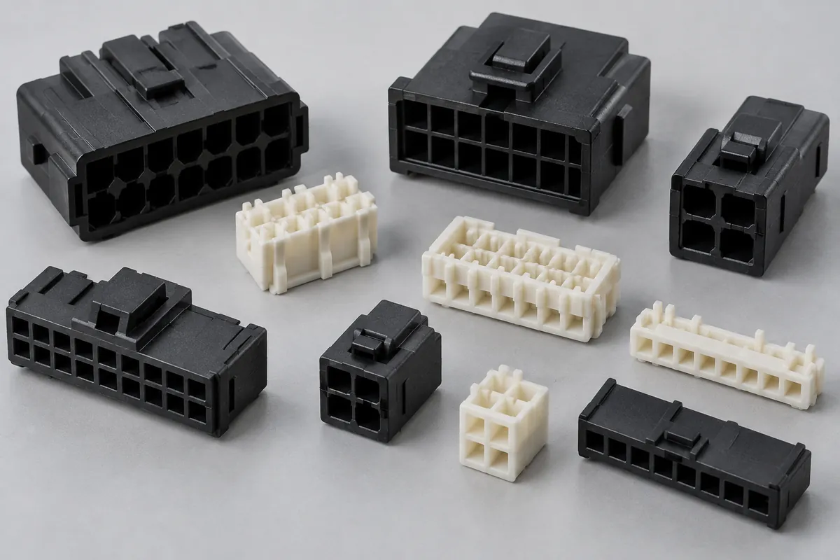
Connector Insulators & Terminal Carriers
Custom molded insulating bodies and terminal carriers. Define terminal interfaces, locating references, exact resin and component acceptance.
Review the application →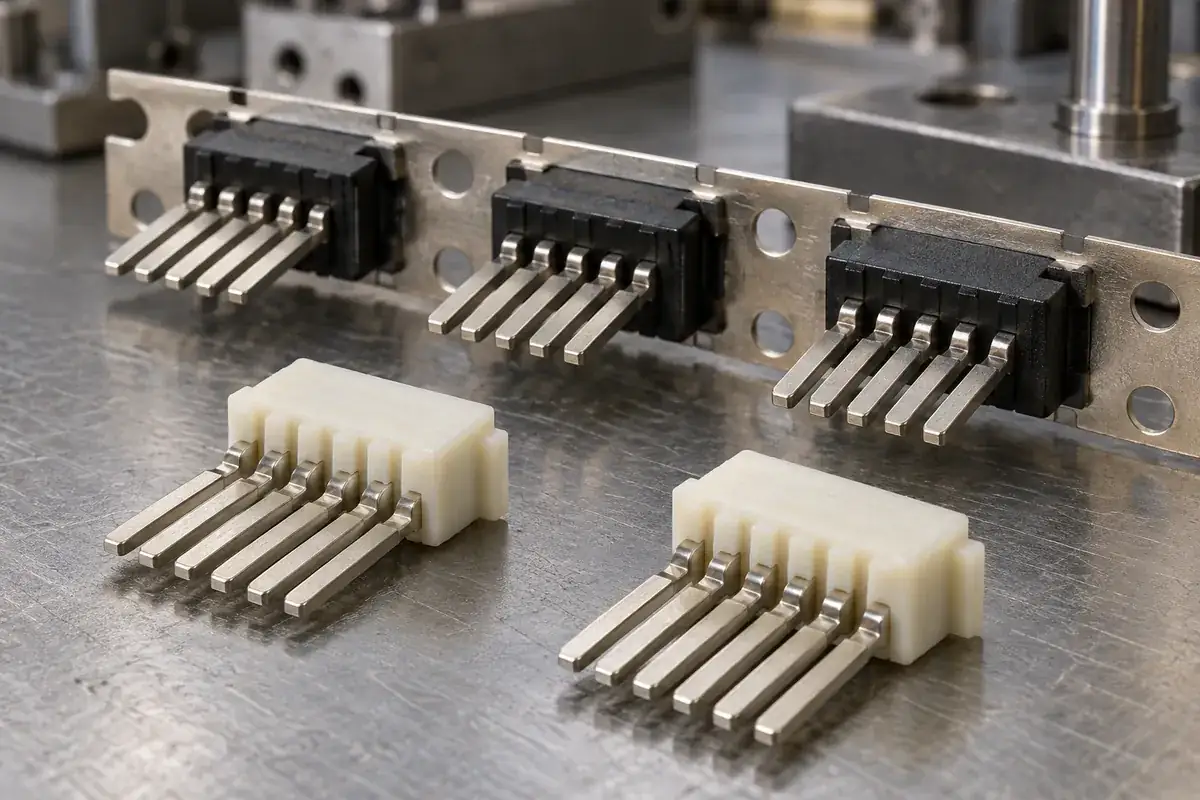
Custom Insert-Molded Connector Components
Custom connector components combining stamped terminals and molded plastic. Review contact location, carrier strips, resin shutoffs, tooling and inspection with FECISION.
Review the application →Before you request a quote
What can this custom manufacturing scope include?
The core scope is molded insulating tongues, terminal carriers and plastic retaining or locating pieces made to an agreed design. Tooling, trial molding, recurring supply, secondary operations, reports and packing are defined in the quotation. Share the assembly context so the proposal covers the required plastic items and interfaces.
Can you supply a complete USB connector or cable from this page?
This page describes custom plastic-component supply. A complete connector combines insulating parts with contacts, shell and other defined elements, while a cable has additional construction and verification requirements. Any complete-assembly work requires a separately reviewed scope and its own acceptance evidence.
Does the molded insulator establish USB performance or certification?
The insulator contributes geometry and support within the assembly. A dimensional report or resin document does not establish a complete connector’s electrical rating, supported data rate or USB-IF status. Those claims must be evaluated for the responsible complete-product configuration under its applicable requirements.
Which material should the tongue use?
Provide the approved exact grade if one exists. Otherwise, review candidate grades against thin-section filling, dimensional behavior, assembly loading and the actual downstream exposure. Resin-family names alone are insufficient to promise tongue flatness, local weld-line behavior or performance after a specific thermal process.
How should tongue flatness and location be inspected?
Define the controlled surface, functional datums and whether the requirement applies in a free or specified restrained state. A fixture should reproduce that condition without unintentionally flattening the tongue. Location relative to the carrier and shell references may need separate measurements from local surface form.
What should be included with an initial drawing package?
Send the plastic model and drawing, relevant contact and shell geometry, assembly sequence, material and exposure requirements, critical feature list and expected quantities. Add gate and ejector restrictions, sample-report needs and protected packing surfaces so those requirements can be considered before the tooling proposal is fixed.
Your next step
Discuss the part with its intended function.
Send the plastic drawing together with the contact paths, shell references and installation sequence it serves. We will review the tongue, carrier or retaining part as a defined molding program, with practical tooling, sample, inspection and packing deliverables.
Explore our connector injection molding service or review other connector components and mold inserts.