
Connector mold components · Made to your tool design
Precision Connector Mold Inserts
Build the forming geometry and its fit in the mold into one controlled tooling definition.
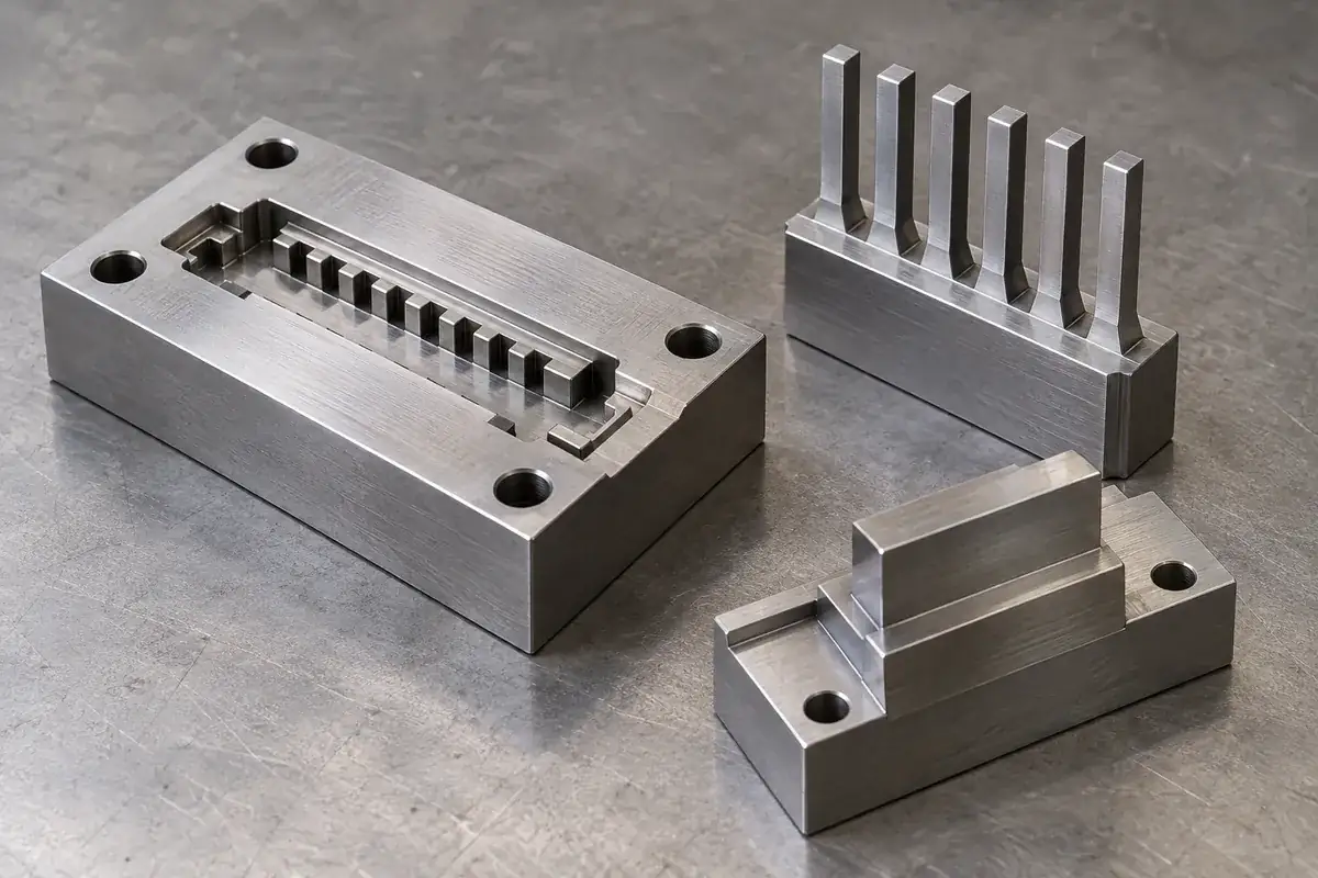
FECISION coordinates custom steel mold inserts for precision connector tooling, including cavity inserts, supported core features and replaceable comb-shaped elements. Share the molded-part geometry together with the insert and mating mold drawings. We review machining access, steel condition, forming surfaces, locating fits and inspection references before defining the manufacturing route.
Product details
The working surfaces and interfaces of a connector mold insert
Product design illustrations show how the forming features connect to a supported base, locating surfaces and a replaceable mold interface.
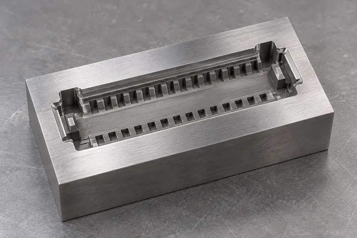
Cavity-forming surfaces
Product design illustration: distinguish the surfaces that form the connector from the surfaces that locate the insert in the mold.
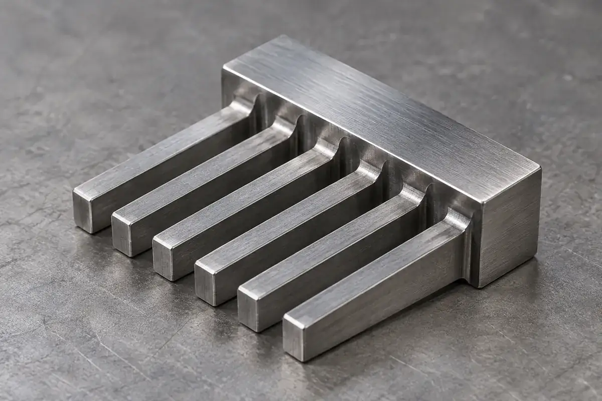
Supported thin cores
Product design illustration: review unsupported length, root geometry and support around narrow core features.
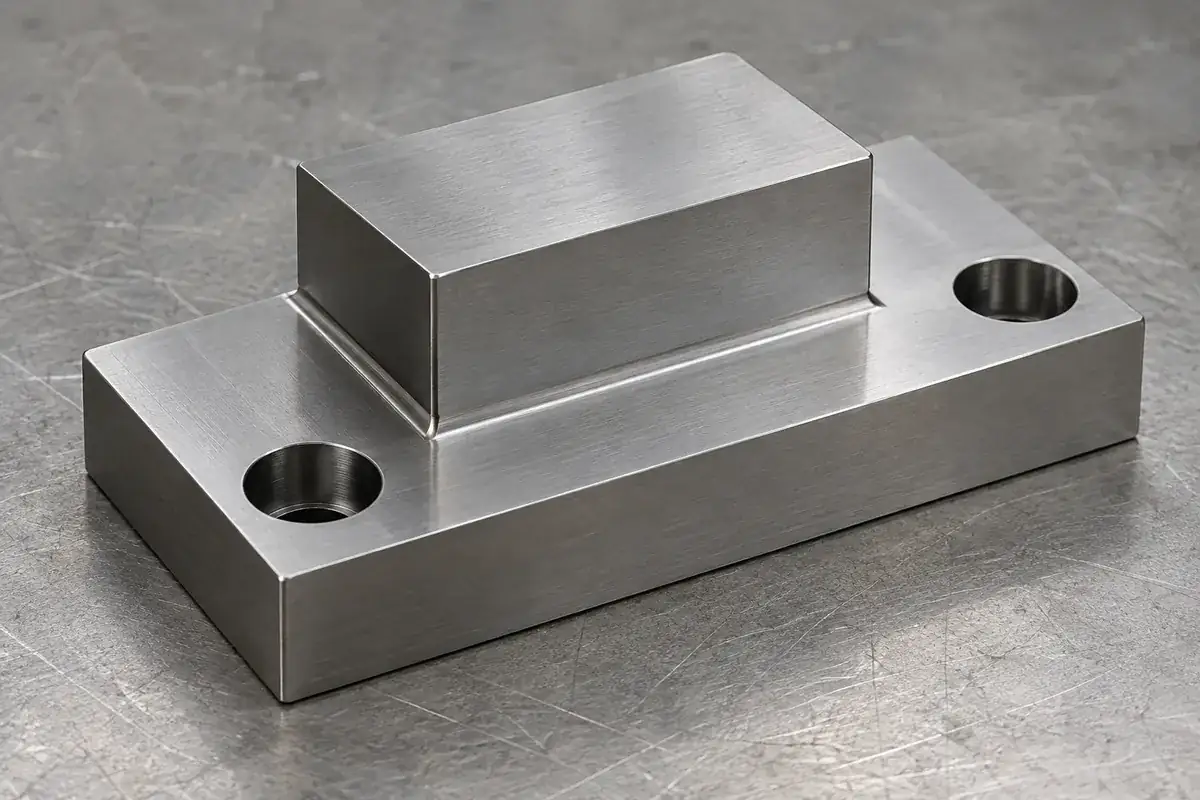
Locating and retaining features
Product design illustration: define the locating faces, retention method and datum scheme against the mating mold pocket.
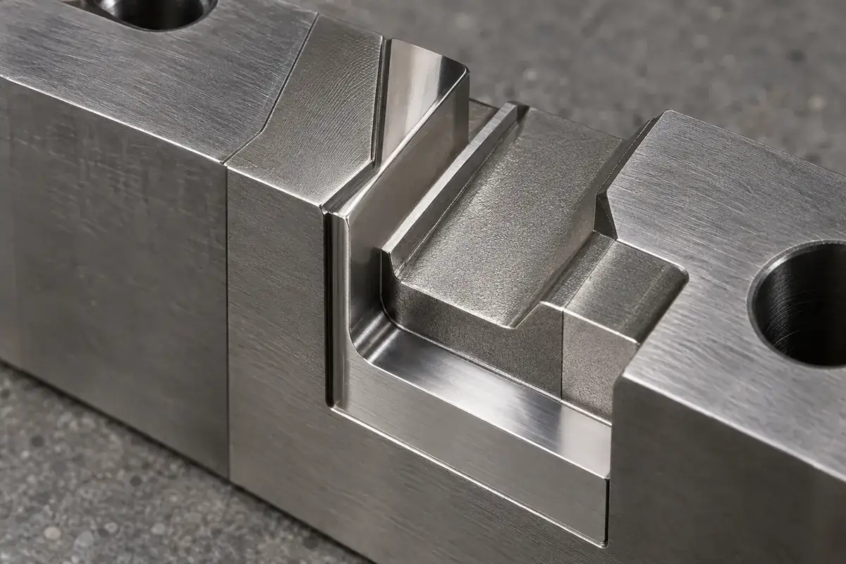
Edges and finishing transitions
Product design illustration: specify where a sharp edge, controlled radius, surface finish or relief must be preserved.
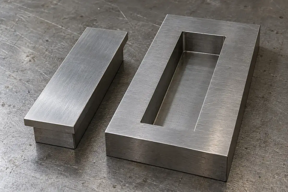
Replaceable mold interface
Product design illustration: a replacement needs the surrounding interface definition as well as the forming geometry.
Illustrative configurations. Final specifications follow your approved drawings.
Application fit
Tooling components for connector molding programs
A fine cavity detail is only useful when the insert can be located, supported, finished and maintained in the intended mold. Review the insert as part of that assembly, whether you are developing new tooling or replacing a worn component.
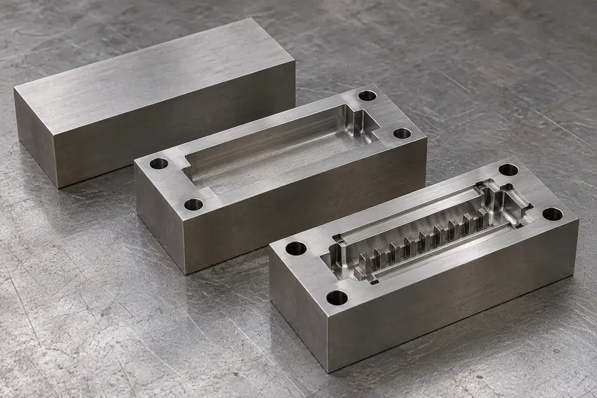
Cavity and profile inserts
Custom steel inserts that form connector walls, pockets and external profiles. Defining them as separate tooling elements can improve access for machining and finishing, but each split also adds an interface that must be located and sealed correctly.
Thin cores and comb-shaped elements
Closely spaced forming features for connector openings and internal details. Review the feature roots, available backing and removal direction together. The manufacturing method and the support in the assembled tool both affect whether a narrow feature is practical.
Replacement inserts and matched spares
Replacement tooling made to the approved insert definition and its mating interfaces. Identify the cavity position, drawing revision and any previous fitting adjustments. Where the original fit is uncertain, inspection of the mating tool may be needed before a replacement can be released.
Quote-ready inputs
What to send for a meaningful quotation
Use the same drawing and requirements for every proposal. Mark open decisions explicitly so that a low price does not conceal a different deliverable.
| Area | Please provide | Review before release |
|---|---|---|
| Geometry and revision | Insert CAD and drawing, molded-part model, revision and cavity identification. | Separate forming surfaces from assembly interfaces and identify narrow, deep or difficult-to-access details. |
| Mating tool interface | Pocket drawing, locating datums, fits, retaining details and surrounding mold geometry. | Review support, assembly direction, shutoff contact and the interfaces needed for replacement. |
| Steel and heat-treatment condition | Specified steel grade, hardness range, supplied-stock condition and any required material documentation. | Agree the machining and heat-treatment sequence, finishing allowance and verification for the selected material. |
| Surface and edge requirements | Finish callouts, texture or polish areas, edge conditions and any EDM surface requirements. | Preserve the features that control sealing and molding while defining where finishing or relief is permitted. |
| Inspection and acceptance | Critical dimensions, datums, measurement methods, reports and any trial-fitting requirement. | Check insert geometry against the tooling drawing and define mold-fit or molded-sample approval separately. |
| Quantity and maintenance | New-tool or replacement purpose, matched-spare quantities, cavity position and known wear history. | Prepare a supply scope that identifies revisions, interchangeable interfaces and any fitting work required at the receiving tool. |
From drawing to approval
From the connector geometry to a maintainable mold insert
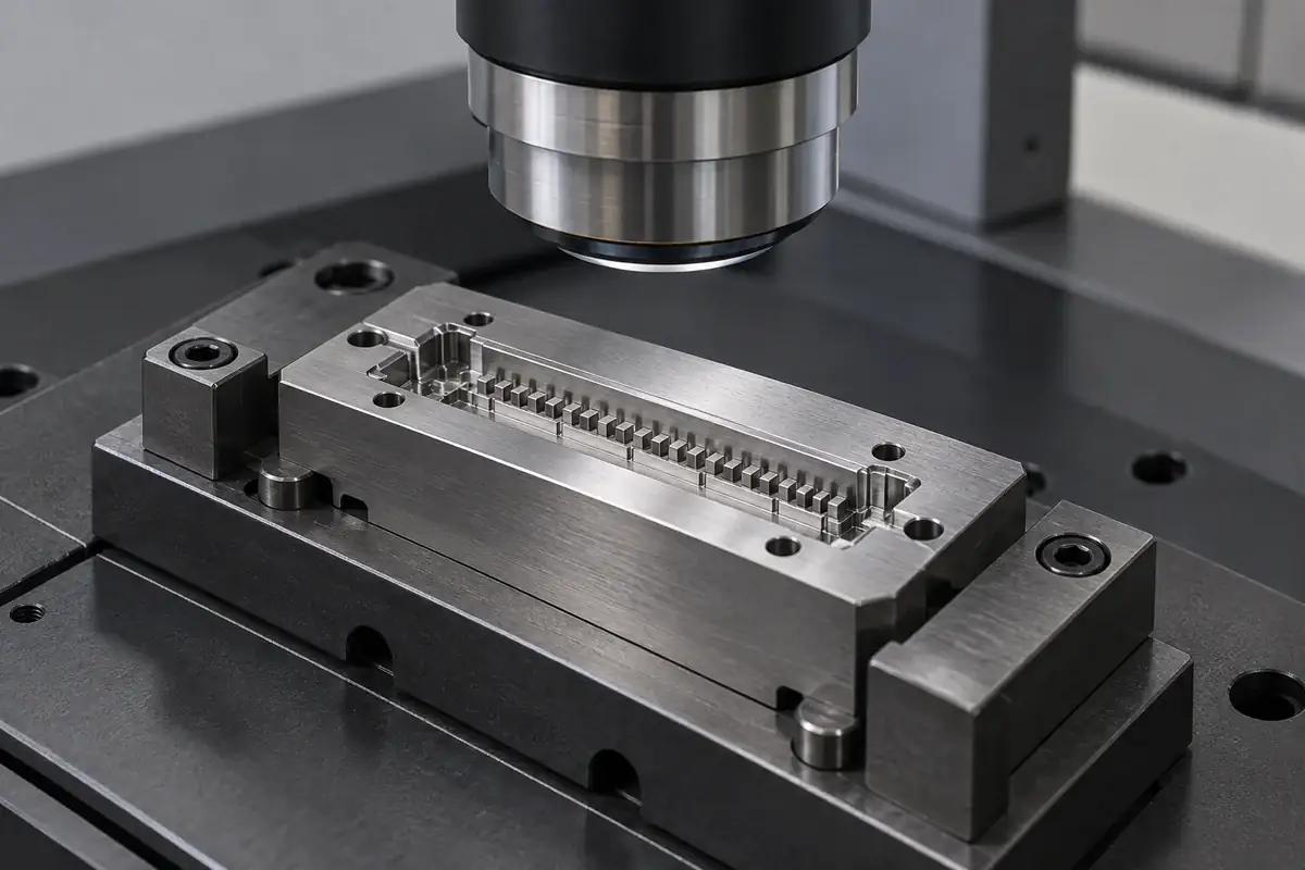
Review the insert in the mold assembly
Start with the molded-part model, then examine the steel that creates each detail. Establish where the insert is supported and located, how it is retained and how it can be removed for maintenance. For replacement work, compare the drawing with the existing assembly and record any known fitting changes.
Choose the steel condition and machining route
Select the route around the specified material and geometry. Milling, grinding and electrical discharge machining serve different access and feature needs. Coordinate any heat treatment with machining allowance and the final dimensional state so that a finished size is not assumed to survive a later process unchanged.
Finish the functional surfaces
Use the drawing to distinguish molding surfaces, locating faces, shutoffs and relief areas. Agree polishing or other finishing after EDM where required, while preserving sharp features and controlled radii. Finishing a cavity surface should not unintentionally change a locating fit or round a sealing edge.
Verify and identify the delivered insert
Inspect the specified features from the agreed datums and identify the insert against its revision and cavity position. Where trial fit or molded samples are part of the order, use those checks to approve the relevant assembly or molding result. Keep spare-insert identification connected to the tool configuration it is intended to replace.
Practical engineering and buying guides
Decisions to make before production
- Connector Mold Inserts vs Molded-In InsertsDistinguish reusable steel connector mold inserts from terminals captured in plastic, then define the drawings, interfaces and inspection scope each needs.
- When Replaceable Inserts Make Sense in Connector MoldsCompare replaceable and monolithic connector mold features through machining access, support, registration, repair scope and the cost of future changes.
- Wire EDM vs Sinker EDM for Connector Mold InsertsChoose wire or sinker EDM around connector insert geometry, electrode access, support, finishing and inspection rather than a generic precision claim.
- Choosing Steel for Precision Connector Mold InsertsBalance wear, toughness, corrosion, finishing and support when selecting steel for connector mold inserts, with grade and condition kept explicit.
- Steel-Safe Adjustments in Precision Connector MoldsPlan connector mold changes around cavity and core directions, trial measurements and replaceable features without treating steel-safe as loose tolerance.
- Connector Mold Insert Datums and Fit InspectionInspect steel connector mold inserts from functional datums. Connect cavity geometry, seating faces, measurement access and assembly fit without confusing them.
- Connector Mold Insert Finish: Preserve the Working EdgesBalance EDM texture, polishing and edge protection on steel connector mold inserts. Specify functional surfaces and inspect geometry after finishing.
- Maintaining Vents in Connector Mold InsertsMaintain connector mold insert vents without changing their geometry. Separate deposits, damage and blocked relief paths, then verify the restart condition.
- Are Spare Connector Mold Inserts Truly Interchangeable?Define what interchangeable means for spare connector mold inserts. Review mounting interfaces, revision control, fitting history and restart verification.
- Connector Mold Inserts: Steel Acceptance and Mold TrialsSeparate steel insert acceptance, mold assembly checks and molded-sample approval. Define trial evidence, open issues and revision status before production.
Related connector manufacturing scopes
Connect the mold-component requirements to the plastic body or terminal-and-plastic component it will produce.
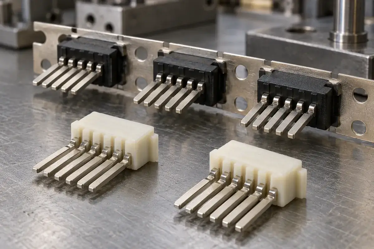
Custom Insert-Molded Connector Components
Custom connector components combining stamped terminals and molded plastic. Review contact location, carrier strips, resin shutoffs, tooling and inspection with FECISION.
Review the application →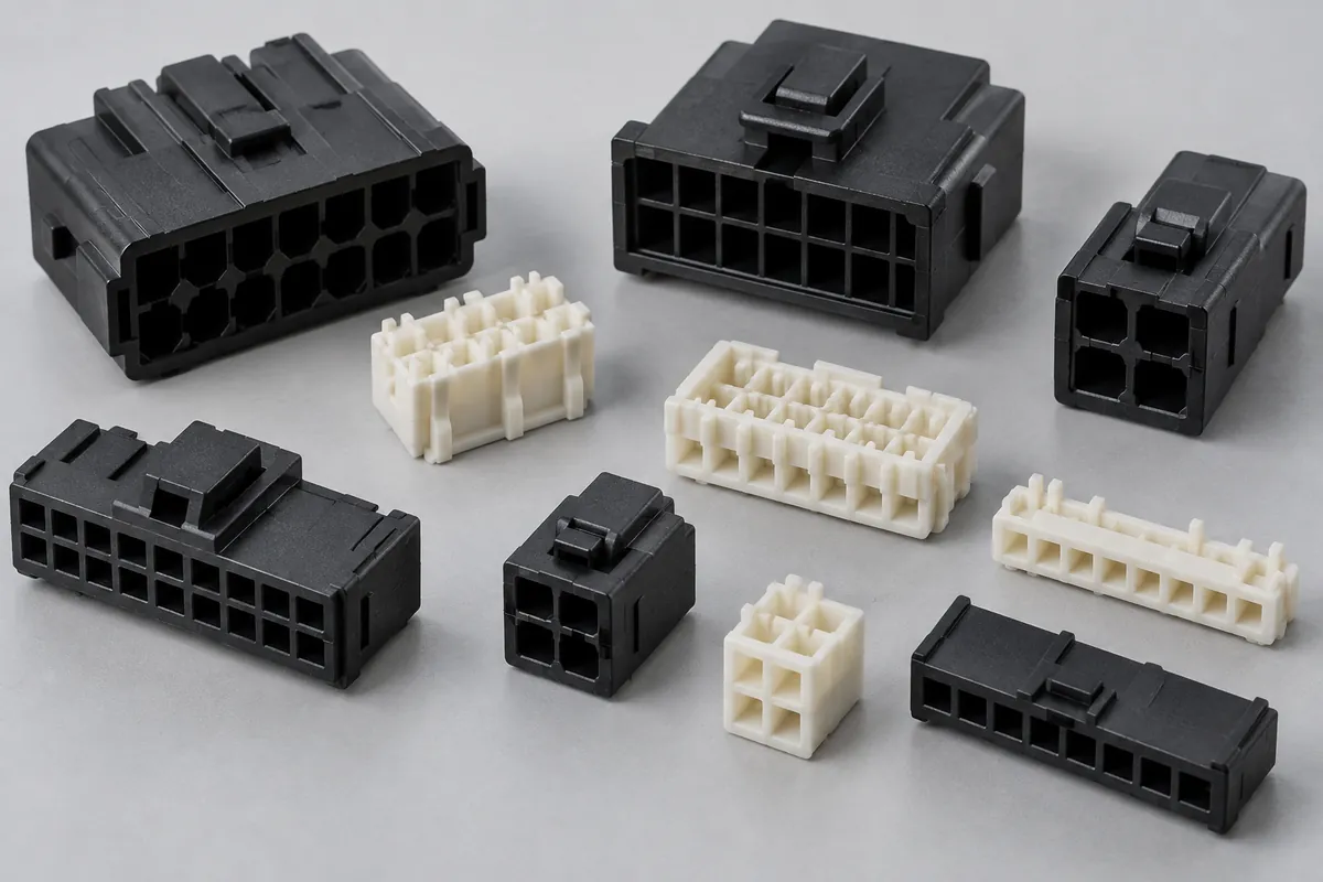
Connector Insulators & Terminal Carriers
Custom molded insulating bodies and terminal carriers. Define terminal interfaces, locating references, exact resin and component acceptance.
Review the application →Before you request a quote
Is this the same as connector insert molding?
No. A mold insert is a steel tooling element that stays in the mold and forms the plastic. In connector insert molding, metal contacts are loaded into the mold and remain inside the delivered plastic component. We can review either scope, but their drawings and manufacturing requirements are different.
Can you quote a replacement from a sample alone?
A sample can support the review, especially if drawings are incomplete. It does not establish the original tolerances, steel condition or intended fit. Share the mating pocket information and any available drawings so the inspection and reconstruction work can be included in the quotation.
Which tool steel should a connector mold insert use?
The choice depends on the molded resin, wear and corrosion exposure, feature geometry, toughness needs and finishing requirements. Provide an approved grade where one exists. Otherwise, steel selection and heat-treatment requirements can be reviewed as part of the tooling scope.
Are replacement inserts automatically interchangeable?
Interchangeability needs a defined locating and fitting scheme. Previous hand fitting, wear or drawing changes can affect the result. Agree the interface dimensions, reference state and any trial fit required before treating a new insert as a drop-in spare.
What tolerance can you offer on fine connector features?
Send the feature dimensions, datums and acceptance method for review. Thin features, access, steel condition and finishing influence the feasible route. We agree tolerances for the specific tooling drawing; the resulting plastic dimensions also depend on the mold assembly, resin and molding process.
Can the order include inspection and material documents?
Specify the required dimensional report, steel documentation, hardness verification and any other records at quotation. Also identify whether the order includes standalone insert inspection, trial fit in the mold or approval of molded samples, since these check different aspects of the tooling program.
Your next step
Discuss the insert with its mold interfaces.
Send the insert drawing, mating mold interface and connector model together. We will review the forming details, support and finishing requirements so your quotation covers the tooling component you actually need.
Explore our connector mold tooling service or review other connector components and mold inserts.