
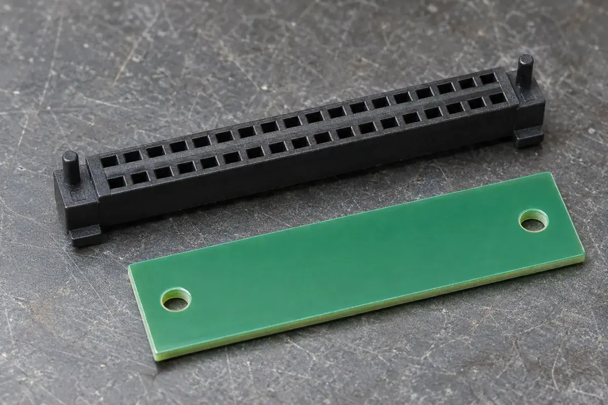
A molded peg can help place a connector housing on a board, but its presence does not explain whether it locates, retains or merely guides the part. Those roles require different fits. A peg made tight enough to hold a housing during handling can also prevent its seating feet from reaching the board or fight the location established by another feature.
The first design decision is therefore functional: what should the peg control at each stage of assembly? Before attachment, it might help orientation. During placement, it might guide the part toward a footprint. After attachment, it might have no structural role. Treating all three stages as one permanent interference fit often creates unnecessary constraints.
Product design illustrations accompany the engineering explanations below.
Locate the housing without asking every feature to locate it
Identify the board references that establish the connector's final position. Depending on the assembly, these may include placement coordinates, contact attachment features, mechanical fasteners or the peg pattern itself. If several systems demand an exact location, their tolerances must agree. Otherwise, one feature is forced to deform or another fails to seat.
Two round pegs in two round holes constrain both lateral position and the distance between the holes. That arrangement may be appropriate when the variation is controlled. It can also become sensitive to differences between molded peg spacing and the board hole pattern. The relevant requirement is the pattern relationship, not just the diameter of each individual peg.
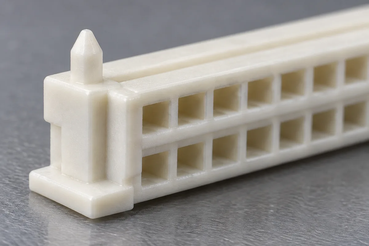
One possible alternative uses a primary round feature and a relieved secondary feature. The first establishes position; the second controls rotation while allowing selected spacing variation. This is a locating principle rather than a universal recommendation. The direction of relief must correspond to the variation the assembly needs to accommodate, and the remaining control must still satisfy its function.
Samtec's alignment discussion describes alignment pins as aids to placement and polarization. A peg should therefore receive a specific assigned role; its existence alone does not prove the final accuracy of the complete board-to-board interface.
Separate the entrance from the controlling fit
A tapered tip can help the peg find a hole without defining the fit farther along the shaft. The controlling section should be identified in the drawing. Measuring only the tip may show ample clearance while the full peg binds. Measuring a drafted peg at an unspecified height can also produce apparently contradictory inspection results.
The board hole has its own physical condition. Its drawing should identify the relevant finished geometry and whether plating or another process affects it. Do not assume that a nominal drill size is the final mating diameter. The housing and board teams need to use compatible definitions before calculating clearance or interference.
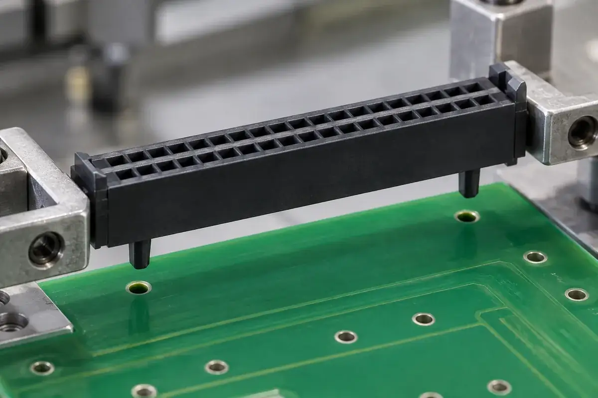
Evaluate the smallest available clearance for correct installation and the largest clearance for adequate guidance. Those two conditions can lead to different concerns. A larger gap may be acceptable before a later process establishes location, while a tight gap may be essential if the peg is the final datum. The assembly sequence determines which concern governs.
Peg length also matters. A peg that bottoms against another component or fixture can hold the housing above the board. A long projection may interfere with equipment on the opposite side. A short peg may enter too late to provide useful guidance. Include the board thickness and underside envelope in the review rather than stopping at a top view.
Keep seating loads out of unintended plastic sections
The seating feet should reach their intended support plane without requiring the housing to bend around a tight peg. If the peg carries the final press load through its tip, the resulting housing height can depend on the board hole and fixture condition. That is a different arrangement from a housing seated on defined feet and should be treated explicitly.
A snap or compliant peg deliberately adds retention. It needs room to deflect during insertion and a receiving geometry that supports the intended final state. The flexing region should be evaluated with the selected material and assembly conditions. A solid locating pin should not be assumed to behave like a compliant retention feature merely because plastic can deform.
Interference can transfer stress into the peg root and adjacent housing wall. Increasing the root section may reduce one local concern while changing molding behavior or the available board clearance. Examine the whole transition and the force path. A dimensional fit calculation is necessary but does not by itself establish repeated-assembly durability.
When a housing is fixed to the board, its peg pattern also establishes a relationship to the mating connector. A small local adjustment can shift the entire cavity pattern. This is why mezzanine alignment and peg fit should share datums. Solving placement difficulty by loosening a feature may move uncertainty into the later mating operation.
Inspect a peg as part of a pattern and a seating system
A useful report separates peg size, peg position and peg-to-seat relationship. Each answers a different assembly question. A diameter result cannot establish that two pegs match the board pattern. A pattern result cannot establish that the housing will sit flat. Keep the inspection structure close to the actual way the part meets the board.
A board-representative fixture can reveal combined installation behavior, provided its hole geometry and condition are controlled. Repeated use may wear a fixture or contaminate a hole, changing the result. Identify the fixture and its verification status rather than treating any spare board as a permanent gauge. Component dimensions remain useful for diagnosing a failed combined check.
Development samples should be evaluated with the intended insertion direction and support beneath the board. Unsupported board flex can make a tight fit appear workable while transferring load into surrounding components. Conversely, an overly rigid test fixture can hide movement that the production assembly intentionally permits. Match the test boundary to the agreed process.
For custom molded board-to-board housings, share the board-hole definition, seating references and attachment sequence. The broader connector insulator manufacturing scope addresses molding feasibility; peg acceptance should explain how the housing enters, seats and becomes located on the actual board.