
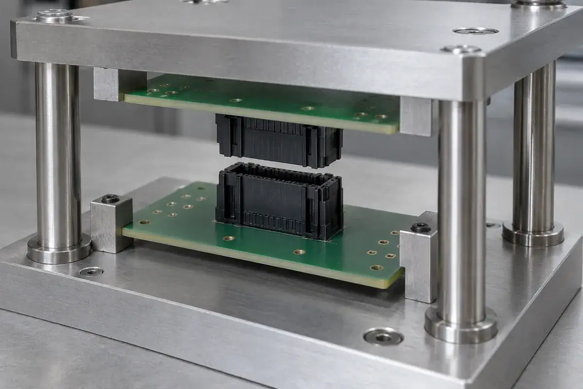
A connector can be fully engaged before an assembly machine finishes its stroke. If the machine continues moving, the remaining travel must go somewhere: into a designed compliant element, board bending, housing deformation or another part of the structure. Calling that movement overtravel does not make it harmless. Its destination and allowable extent must be defined.
In a board-to-board assembly, the final position may be controlled by a press, standoffs, fasteners or enclosure features. The plastic housing may have a seating shoulder, yet that shoulder is not automatically intended to carry the force generated by the entire system. Review the assembly beyond first engagement to see which surfaces actually stop the motion.
Product design illustrations accompany the engineering explanations below.
Distinguish engagement from the stopping mechanism
Engagement describes the intended relationship between mating members. A mechanical stop establishes the travel limit. These can occur at the same nominal position, but they are different functions. If the housing supplies both, its structural role must be explicit. If another component supplies the stop, its tolerance relationship to the connector becomes critical.
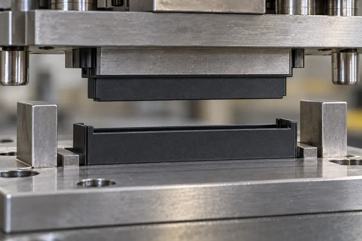
Map the sequence from initial guide contact to final board position. Identify when the housing guides overlap, when the contacts enter their intended range and when the first hard stop is reached. The contact system's permitted travel must come from its approved definition. An empty housing model cannot establish how much additional contact deflection is acceptable.
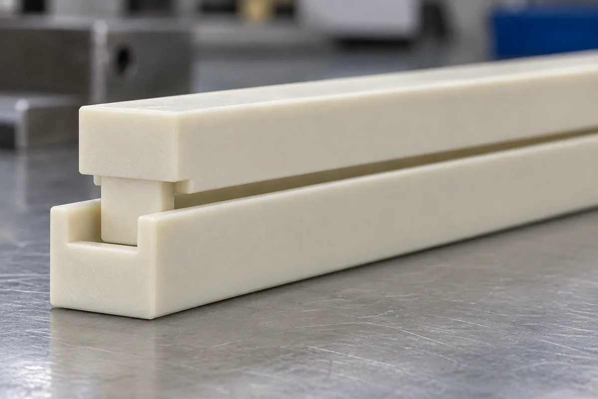
A housing shoulder can provide a clear positional reference but concentrates load into its bearing area. A wider shoulder may spread that load, while also consuming board space or changing the molded section. The adjoining wall and root geometry determine how the load reaches the mounting features. Do not assess a stop surface independently of the structure behind it.
Hirose's DF40 catalog warns against excessive mating force and calls for separate board support. Those product-specific cautions support reviewing the assembly load path rather than assuming the connector should absorb whatever force the board installation creates.
Follow tolerance extremes through the final stroke
The nominal stroke may align perfectly with nominal connector height. Real assemblies include variation in housing seating, board thickness, supports and machine references. At one extreme, the stroke may stop short of the intended engagement. At the other, the same commanded motion may compress an already seated connector. Evaluate both conditions with the same reference chain.
The stack-height analysis establishes the geometric relationship. Overtravel analysis adds what happens when motion continues after one interface closes. A dimensional difference is not merely a gap on a drawing once the equipment applies load. Determine which member is compliant and whether that compliance is intentional and qualified.
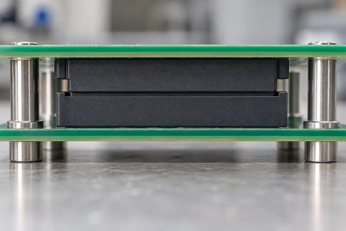
Fasteners create a similar issue. Tightening a board against standoffs can pull the board past the connector's intended position if the supports are too short. The installation may appear successful because the screws reach their seats. That observation confirms the hardware condition, not the absence of connector compression. The local board shape and connector relationship still need evaluation.
Supports placed far from the connector can allow local bending even when their nominal heights are correct. Moving support closer can reduce that motion, but may compete with routing, component access or thermal design. The mechanical team should evaluate the trade-off at system level. Increasing housing stiffness alone may simply transfer more load into the board or attachments.
Force control and position control answer different questions
A position-controlled process limits motion relative to a machine reference. It can be repeatable while still applying excessive force if the assembled stack is shorter than expected. A force-controlled process limits a measured load, but may stop early because of misalignment or friction. Neither control mode independently proves correct engagement.
A combined evaluation can use position and force information to distinguish the expected sequence from an obstruction. The relevant signatures and limits require development with the actual assembly; they should not be invented from a housing drawing. A rising force before the guides align means something different from a load increase at the intended stop.
Compliance in a fixture can accommodate variation, but it also changes how travel reaches the connector. Too much uncontrolled movement may conceal incomplete seating or allow tilt. A deliberately compliant element should have a known direction, range and reference state. It should not depend on bending a delicate housing wall whose geometry was intended only for guidance.
Assembly speed can also influence observation and control response. A process that appears benign during slow manual mating may behave differently in production equipment. Rather than assigning a generic speed limit, include the actual motion profile in development. The objective is evidence for the intended process, with the same supports and counterpart condition.
Inspect for the mechanism, not only the aftermath
Visible cracks are a late and incomplete indicator of excessive travel. A housing may remain intact while a contact moves, a board bows or an attachment is stressed. Development checks should observe the stop relationship and engagement state directly where possible. A cosmetic inspection alone cannot establish that the assembly stayed within its approved mechanical conditions.
Retain the counterpart revision, support dimensions and equipment setup with any evaluation result. A successful test using a slightly taller spacer does not approve a shorter production spacer. Likewise, an empty-shell mating check does not reproduce the load from a populated contact system. Keep each result attached to the configuration it actually tested.
Where a stop feature is changed, revisit adjacent guide and key geometry. Moving a shoulder can alter when a polarization key engages or how much straight guidance remains. The change may solve compression while creating an alignment problem. Review the full motion again rather than treating the edited dimension as an isolated correction.
For custom board-to-board housing manufacture, define which molded surfaces guide, seat and carry stop loads. The broader connector insulator review can address component production. Approval of the final assembly should additionally show where excess motion goes and how the process prevents it from damaging the intended interfaces.