
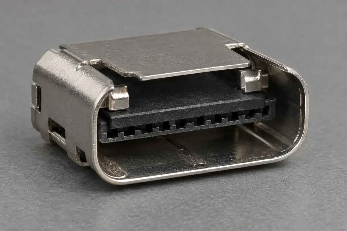
A molded tongue can satisfy its own width and thickness measurements yet sit too high, too far forward or at an angle inside the shell. The missing information is often the locating chain. The assembly does not position the tongue from every outside surface at once. It uses particular shoulders, stops and contact regions, and their relationships determine where the functional geometry ends up.
A datum stack review follows that chain from the shell reference to the plastic locating surfaces and then to the tongue. It is more useful than tightening every dimension because it identifies which relationships actually contribute to the assembled position. It also reveals when an inspection fixture uses a convenient surface that the real assembly never touches.
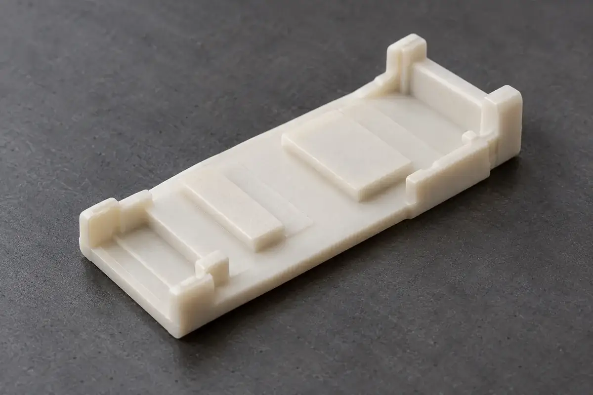
Product design illustrations show the molded components and their assembly relationships.
Start at the surfaces that stop movement
Identify the features that constrain the carrier in each relevant direction. A broad seat may establish height, a rear stop may set insertion depth and a side shoulder may control lateral location. Retaining tabs may hold that position without serving as precise locating surfaces. Distinguishing location from retention prevents a flexible latch from being treated as a rigid measurement datum without justification.
Contact is not always distributed over an entire nominal plane. A molded relief, shell embossment or local high point may create a smaller real contact region. If the design depends on a particular seat, show its functional extent and condition. The inspection nest should reproduce that intended relationship rather than create a larger support plane that changes how the carrier settles.
The order in which surfaces engage can also matter. A side rib might touch the shell before the rear shoulder reaches its stop. If that early contact steers the carrier, the final position may depend on insertion direction or force. Looking only at the fully seated CAD model can conceal this behavior; review the approach and seating sequence as well.
Manufacturer information such as Hirose’s CX series documentation illustrates the presence of insulators and shells within connector constructions. It supplies assembly context, not a substitute datum scheme for a custom part. The actual locating chain must follow the approved drawings for the configuration being manufactured.
Build a short, explicit dimensional chain
For a vertical tongue position, one relationship may connect the shell opening to its internal seat. Another connects that seat to the plastic carrier support surface. A third connects the support surface to the tongue region of interest. Writing those relationships explicitly is more informative than comparing unrelated overall heights measured from the bench.
An axial chain follows a similar logic through the shell stop, carrier shoulder and tongue end. A lateral chain may involve the side locator and the tongue center region. These directions should be evaluated separately before considering combined angular effects. Mixing them into one overall fit judgment can make a clear axial interference look like a general molding-accuracy problem.
Where a part is flexible, the chain includes a defined physical state as well as geometry. A tongue displaced by assembly loading is not described fully by free-state dimensions. The drawing and verification plan should state whether a restraint is intentional and how it is applied. Otherwise, the same part can generate different results in two apparently reasonable fixtures.
The method used to combine tolerances should reflect the design and available evidence. A worst-case review and a statistical study answer different questions and require different assumptions. Avoid claiming a probabilistic fit merely because nominal dimensions line up. Early in development, an explicit chain often exposes missing information before any detailed calculation is justified.
Make the fixture answer the same question
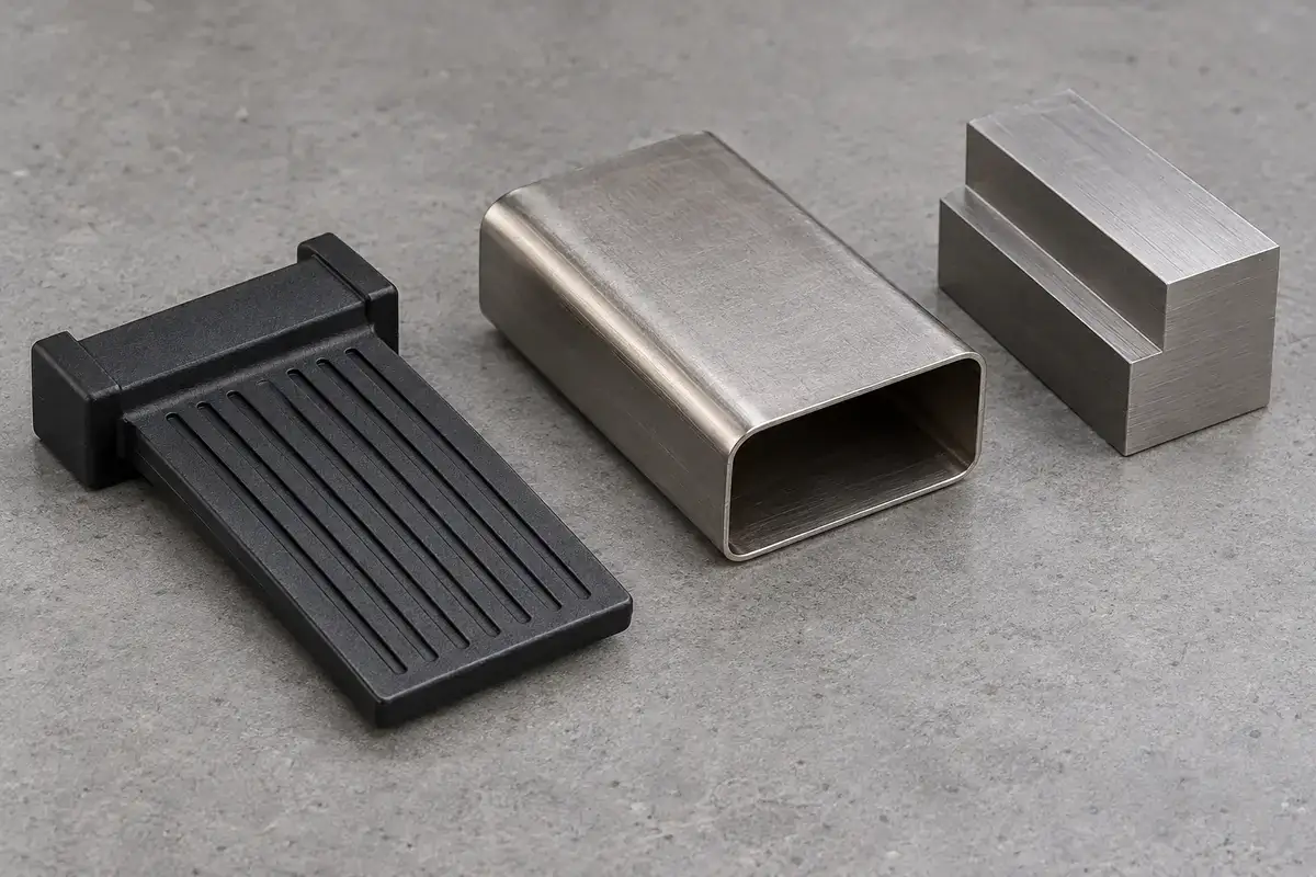
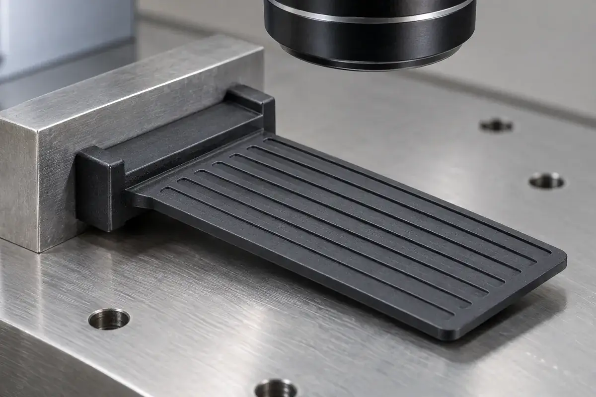
A free-part fixture can locate the carrier from selected datums while leaving the tongue accessible to inspection. Its stops must be placed so that loading does not bend a thin region or push the part into a position unavailable in the assembly. The fixture drawing should identify contact points and any clamp action, especially where the component can rock between alternative seats.
A functional shell gauge can answer whether the component enters and seats in a representative envelope. It may be valuable during development or agreed acceptance. However, a pass does not explain which dimensions control the result, and a failure does not identify the responsible component. Use dimensional evidence alongside the functional check when diagnosing the locating chain.
Repeated loading of one sample is a useful way to assess the method. If the tongue position changes when the operator reseats the carrier, the fixture may allow an unresolved degree of freedom or apply variable force. Investigate that before interpreting small differences between cavities as molding variation. Measurement repeatability is part of the evidence, not an assumption.
The tongue flatness and support guide explains why restrained and free-state observations must remain distinct. The present question is the relationship to the shell. Keeping both measurements available can distinguish a locally bowed tongue from a correctly shaped tongue that is positioned incorrectly by its carrier shoulders.
Investigate the chain before changing the tool
Suppose a tongue appears too far forward in an assembly. Shortening the tongue might restore clearance in one sample, but the original cause could be a carrier that did not reach the intended rear stop. That correction would leave the seating problem in place and alter a functional feature unnecessarily. Check the stop contact and assembly state before assigning the deviation to tongue length.
The same caution applies to angular position. A burr on a shell seat or an ejector witness on a plastic locating pad can tilt the carrier. The measured effect at the tongue tip may be much more noticeable than the local obstruction. The appropriate response is to investigate that contact rather than automatically modify the entire tongue surface.
When either component changes revision, review the corresponding chain. A shell supplier may alter a forming detail that appears remote from the mating opening but changes an internal seat. A plastic tooling change may move a support pad while preserving overall size. Revision control should include the interface relationship, not only a list of changed nominal dimensions.
For related assembly effects, read plastic damage during shell installation. Interference and damage often occur along the same locating path. Understanding that path can show whether the design needs a lead-in, a different support condition or a controlled change to one interface rather than tighter tolerances everywhere.
When discussing custom USB insulating components, include the shell’s relevant seats and stops with the plastic drawing. A supplier can then review molding and inspection against the references that the finished assembly actually uses.
A clear datum chain makes both good and bad results more informative. It connects a measured plastic feature to its assembled purpose, reduces the temptation to correct the wrong surface and provides a stable reference when tooling or counterpart revisions change.