
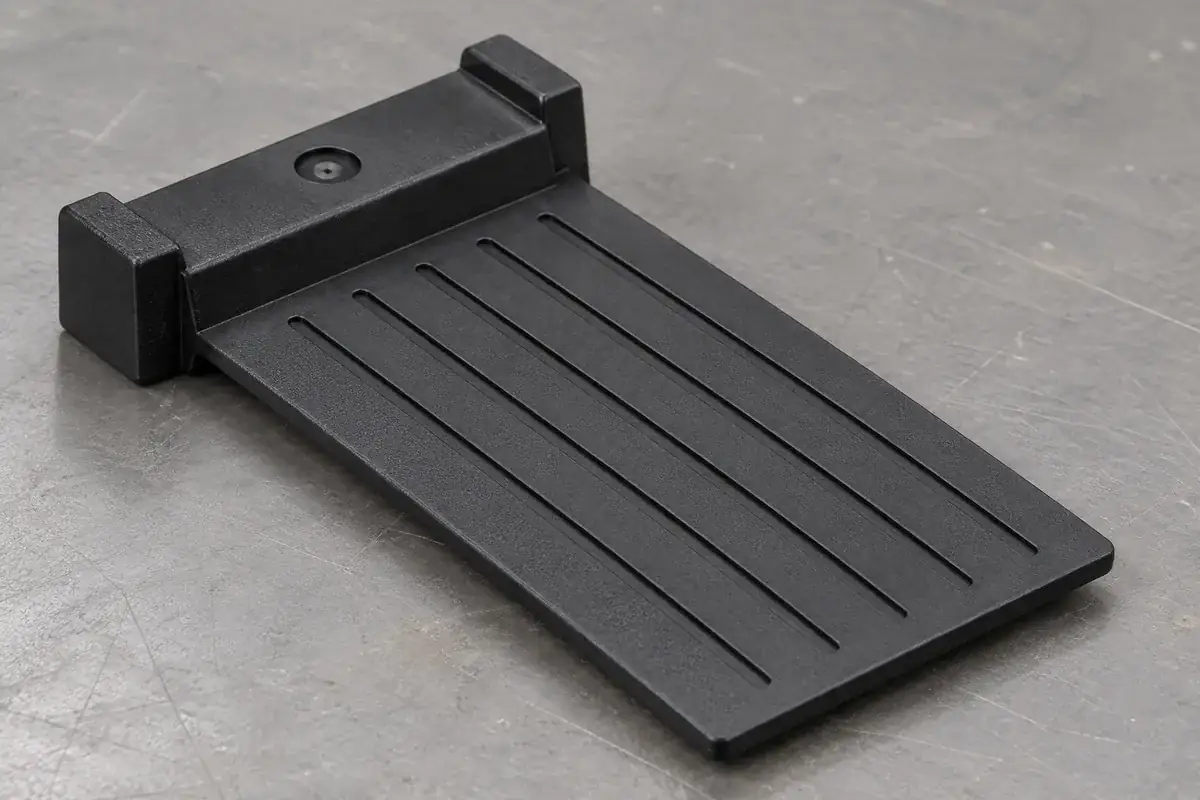
The gate is both an entrance for molten polymer and the origin of a remaining witness on the molded component. For a USB insulating tongue, these two roles can pull the design in different directions. A position that produces a convenient flow path may leave a vestige near a shell seat. A hidden location may be difficult to trim without loading the thin tongue.
The right discussion therefore begins before the gate is treated as a small cosmetic detail. Review the route into the tongue, the material surrounding the gate and the space available after assembly. The objective is a manufacturable filling arrangement with a controlled remaining feature that does not interfere with the plastic part’s intended interfaces.
Product design illustrations show the molded components and their assembly relationships.
Describe the remaining feature in three dimensions
A gate witness can stand proud, sit within a recess or leave a local indentation after separation. Each condition changes a different part of the interface. A height limit alone may miss lateral spread into an adjacent locating shoulder. Define the permitted region and the relevant envelope so the tool designer understands where the complete remaining feature must fit.
A recessed gate pocket can protect a nearby outer surface, but the pocket itself needs review. It may reduce local section thickness, change the support of a retaining feature or create a place where debris is difficult to see. Recessing the witness is a geometry decision with consequences, not an automatic way to remove the gate from consideration.
The rear carrier often offers more room than the thin forward tongue, yet its surfaces may perform important locating or retaining functions. Identify those functions before selecting a rear gate. A small witness on a seating pad can shift the carrier’s position, while the same witness in a clear noncontact region may have little influence on the assembly.
The shell and insulator datum stack is useful here because it shows which surfaces establish tongue position. Gate restrictions should protect those actual reference regions. Treating every outer surface as equally critical can unnecessarily limit the tooling options without improving the assembled relationship.
Connect the gate to the thin section
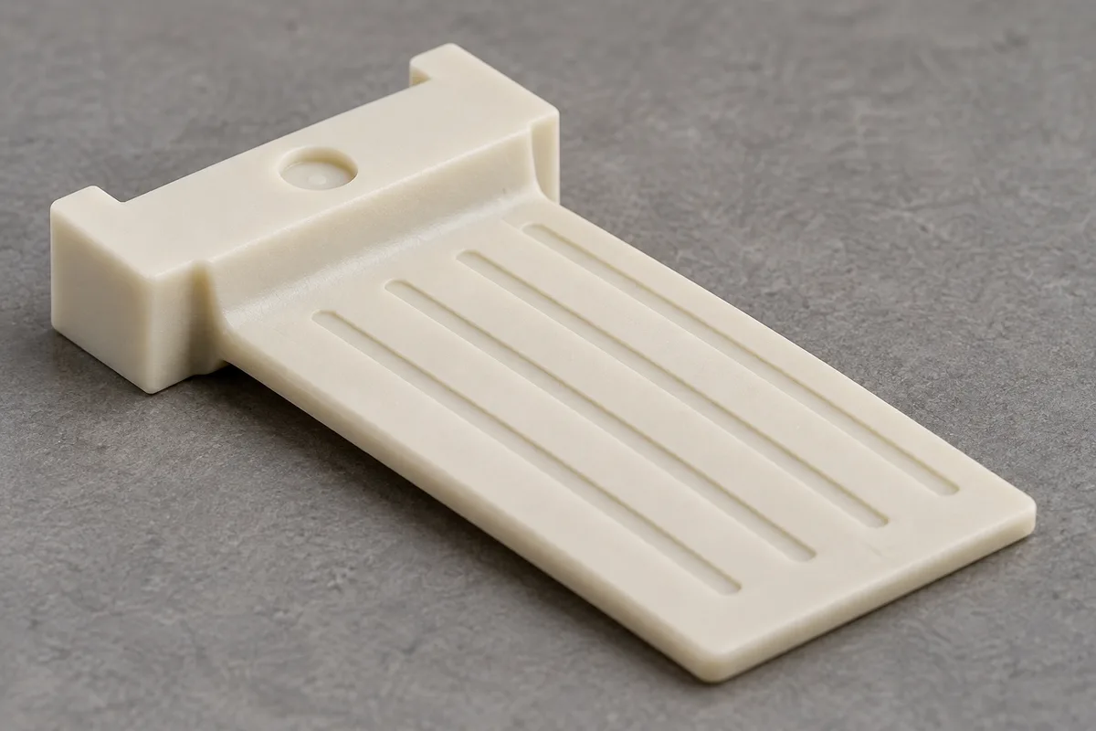
The polymer must travel from the gate through the rear body and into the tongue’s thin regions. Changes in section, interruptions and repeated channels influence that route. A gate selected only for visual concealment can create a less favorable fill pattern. Evaluate whether the proposed location reaches the thin geometry consistently and where separated flow fronts may meet.
The exact resin grade matters to that assessment. Grades within one family can differ in flow behavior and reinforcement. The selected material should be reviewed with its processing guidance rather than represented by a generic claim that all connector plastics fill narrow features easily. The tool and process must still establish the intended geometry in the actual component.
Celanese’s Vectra LCP guide links part design, tooling and molding considerations. For a tongue, that combined view is particularly relevant to the gate choice. It encourages a review of the resulting flow and molded shape rather than selection of a gate from appearance alone.
A proposal for multiple gates may shorten some flow paths but introduce additional meeting fronts and remaining witnesses. A single gate may simplify those relationships while demanding a different route through the carrier. Neither arrangement is universally correct. Compare the alternatives against the thin features, expected weld-line regions and available nonfunctional space for the gate.
Plan separation without bending the tongue
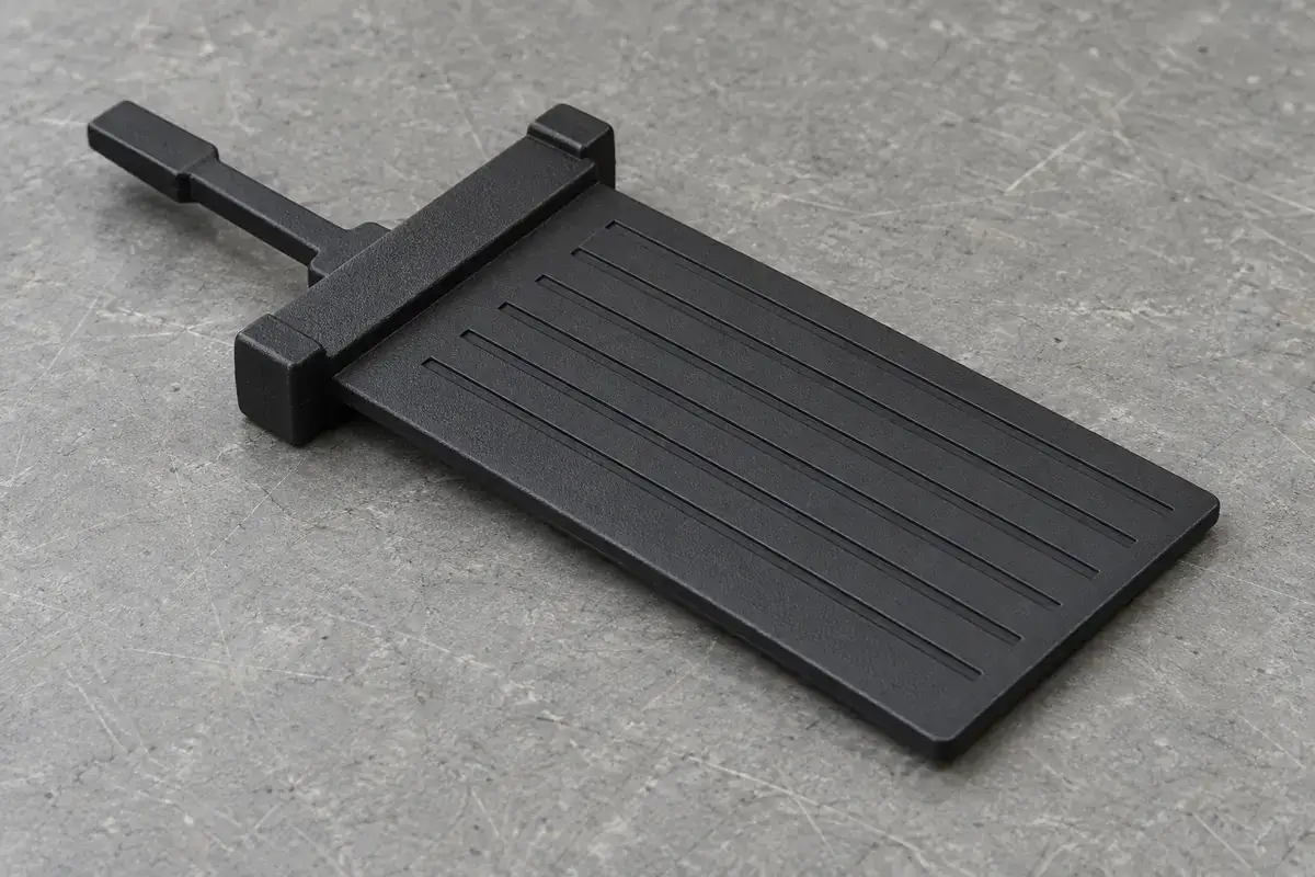
Gate removal applies force to the molded part. If the carrier is supported poorly, that force can pass through the thin tongue or a narrow retaining rib. A trimming operation that leaves a visually neat witness can still introduce a crack or permanent distortion elsewhere. The support and cutting direction therefore belong in the manufacturing review.
Where a dedicated support is proposed, it should react the separation force near the gate through a sufficiently robust region. It should not rely on pressing the tongue against a flat surface simply because that makes the component easy to hold. The support geometry must also leave room for the separation tool and for removal of the cut material.
Automated separation and manual trimming have different sources of variation, but both need a controlled result. Define the remaining envelope, permitted local damage and any required cleaning or inspection. Avoid using an approved early sample as the only description of an inaccessible witness; a drawing or clear acceptance view makes the requirement transferable to later production.
Inspect the gate region before and after representative handling where debris is a concern. A loose edge may remain attached during the first visual check and detach later. The cleanliness and handling guide explains why a part’s transfer path matters when evaluating such particles, especially around narrow contact channels.
Evaluate gate changes as geometry changes
Moving a gate changes more than the location of the visible mark. It can change flow direction, local packing and the location of meeting fronts. If the component uses a directionally sensitive material, its shape or local mechanical response may also change. A gate relocation should therefore trigger review of the affected functional features and sample evidence.
Development samples should retain the connection between gate configuration, cavity and process condition. Comparing an early sample from one gate with a later sample from another without those records can make a real improvement difficult to explain. It can also hide a trade-off, such as better appearance accompanied by a changed tongue position.
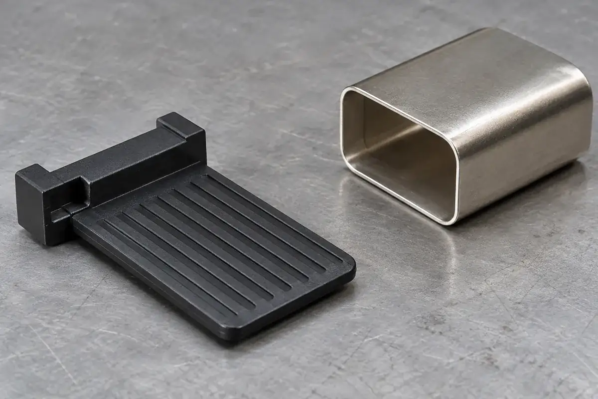
Use the same measurement references when comparing alternatives. Check the tongue, locating shoulders and relevant channels as well as the witness itself. If an assembly evaluation is required, use the controlled shell and terminal configuration. A change to the counterpart at the same time would make the source of an improved fit uncertain.
Some gate choices deserve an explicit development allowance in the tooling plan. A replaceable gate-region insert can support a controlled adjustment where practical, but it adds its own interface and cost. Discuss that option in relation to the uncertainty being resolved rather than treating unlimited gate movement as something available after every tool has been built.
For USB insulator and carrier molding, show the available gate region, prohibited interface zones and intended assembly envelope with the part model. Include how the component can be supported during separation if the thin tongue restricts access.
A well-placed gate is one whose filling route, separation operation and remaining witness have all been considered together. That integrated choice can preserve the functional surfaces while leaving the molding team a practical route to consistent parts and a clearly inspectable result.