
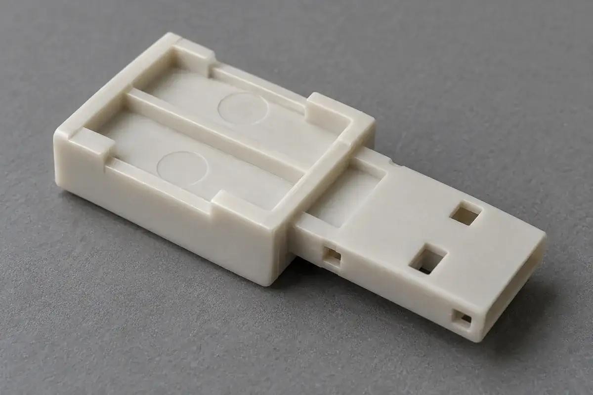
An ejector witness is often discussed as a small circular mark left by a pin. On a USB insulator, the more important question may be what happened while the pin pushed. An uneven release can bend a thin tongue, stress a root or damage a retaining rib. A clean-looking pin mark does not establish that the whole component left the mold without distortion.
Ejection design must connect the surfaces that resist release with the regions strong enough to receive force. For a tongue-and-carrier shape, the available area may be concentrated in the thicker rear body while slender features extend forward. That geometry makes the balance of force, contact and support more significant than the appearance of any one witness.
Product design illustrations show the molded components and their assembly relationships.
Identify the resistance before choosing the pins
The component may grip a core, remain against a cavity surface or catch at a local feature. Draft, texture, steel condition and molded geometry influence that behavior. If one region releases late, pins elsewhere can begin bending the part before it separates. Adding more force without understanding the resistance can make the damage more repeatable instead of resolving it.
Repeated channels and narrow ribs can create a large amount of local surface relative to the size of the part. Their release direction should agree with the tool layout. A small unintended undercut or rough edge near a slot may resist removal even when the main body has adequate draft. Inspect the specific forming region associated with the observed damage.
A thicker rear pad can receive ejector contact more effectively than a thin tongue, but only if the force reaches the resisting region through a suitable load path. A remote pad connected by a narrow bridge may still bend that bridge. Review the shape between the pin and the retained feature, rather than selecting pin locations solely from available flat space.
Celanese’s precision-molding guidance for Vectra LCP covers part and tool design alongside processing. Use the selected grade’s guidance within that review. A resin family associated with precision parts does not remove the need to evaluate release behavior in the actual tongue geometry.
Protect locating surfaces from an uncontrolled witness
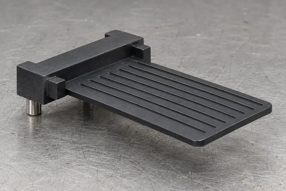
A witness can be recessed, raised or associated with a small surrounding mismatch, depending on the tool design and condition. Its effect depends on location. A small raised region on a shell seat can change the carrier’s angle, while a similar mark in a clear recess may be functionally irrelevant. The acceptance definition should distinguish those surfaces.
If a pin must act near a locating pad, examine whether its contact can sit in an approved relieved region without undermining the support needed during assembly. The relief has to be part of the design definition. Quietly adding a recess after the tool is built can change local stiffness or reduce the actual seating area.
The drawing should identify the permissible witness zone and the relevant surface condition. An overall cosmetic requirement is often too broad to explain a functional seat. Conversely, a highly restrictive finish callout applied everywhere can make an otherwise useful ejection arrangement unnecessarily difficult. Give the tooling team functional priorities rather than one undifferentiated appearance rule.
The shell datum stack helps identify where a witness could change the assembled tongue position. Evaluate the local contact there, not just a photograph of the outside surface. A witness hidden inside the shell can still influence fit if it lies in the locating chain.
Look for distortion beyond the pin circle
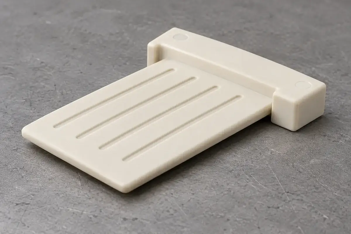
Release-related damage may appear at the tongue root, at a narrow bridge or along a rib away from the ejector location. The pin is where force enters, but the weakest or most constrained region can be elsewhere. Inspect the complete load path when a crack, whitening or local deformation appears during early trials.
A part that relaxes after ejection can also complicate inspection. Define the timing and support condition for comparison, particularly when investigating shape changes. If one sample is measured while warm and another after conditioning, the difference may reflect the sample state rather than a change in the tool. Record the relevant circumstances instead of assigning an unsupported stabilization interval.
Cavity identity can help separate tool geometry from general handling. A consistent mark or distortion in one cavity suggests inspecting that cavity’s release conditions. Similar damage appearing only after transfer suggests examining the collection or packing step. Keep those observations separate until the evidence connects them; both can occur in the same production flow.
See tongue flatness and support for the measurement side of this investigation. A fixture that presses the tongue flat can conceal an ejection-induced shape change. Use a reference state that allows the suspected deformation to remain observable before judging whether the release modification improved it.
Treat release as a coordinated tool and process decision
Possible corrections include addressing a rough forming surface, revising an approved draft feature, improving force balance or changing the release sequence. The evidence should guide the choice. Enlarging a pin may reduce local pressure but consume more space on a critical pad. Relocating it may protect the pad while creating a less direct load path.
Process changes also need evaluation against the rest of the component. A release condition that reduces visible deformation can still affect filling, cycle consistency or another feature. Keep the trial comparison tied to the actual process configuration and inspect the surrounding functional geometry. The objective is a stable part, not merely an attractive witness.
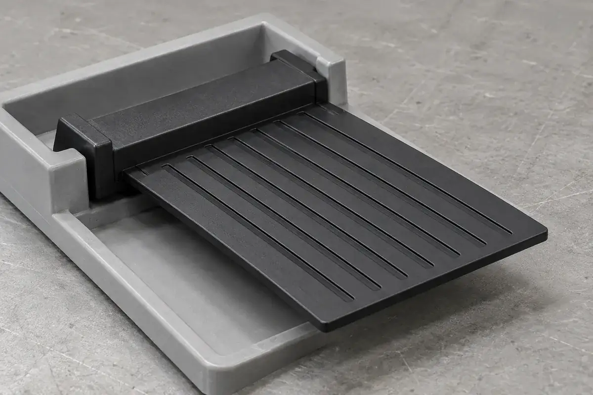
Where a new contact pad or relief is proposed, review its effect in the shell before approving the tool change. A seemingly small plastic modification may alter the support area or interfere during insertion. The same design revision should carry through to the drawing, sample identification and receiving inspection so that all parties evaluate the intended geometry.
After the molding result is satisfactory, examine how the part leaves the machine and reaches its tray. A thin tongue can be damaged by an uncontrolled drop or by accumulation with other parts. The handling guide extends the same support principle into transfer and packing, where a well-ejected component still needs protection.
For custom USB insulating parts, identify the critical seating areas and thin sections before the ejection layout is fixed. This gives the tooling review room to place force where the geometry can receive it and define witnesses where they can be inspected meaningfully.
A successful ejection plan leaves both an acceptable local surface and a component with the intended shape. Evaluating those outcomes together makes it possible to distinguish a harmless tooling witness from an indication of a release problem that could affect the later assembly.