
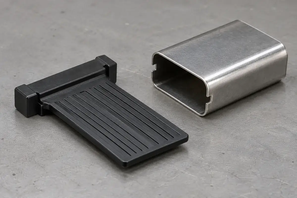
When a plastic carrier is damaged during shell installation, the first suspicion often falls on the plastic material. Yet the same damage can arise from a sharp entry edge, a tilted insertion path, a misplaced locating rib or support that forces a thin section to carry the assembly load. Material selection matters, but it is only one part of the mechanism.
A useful investigation follows the component from its unassembled state through initial contact, guidance and final seating. That sequence reveals where the resistance begins and which region reacts to it. It also separates molding defects that already existed from damage created by the assembly operation, a distinction that can otherwise disappear once the carrier is enclosed.
Product design illustrations show the molded components and their assembly relationships.
Preserve evidence before changing the process
Inspect identified plastic samples before installation. Record the state of the lead-ins, retaining ribs, tongue root and relevant shoulders. After assembly, compare the same regions where access permits, or use a controlled investigation method that does not introduce misleading damage during disassembly. A scratched part removed with improvised tools cannot by itself establish when the scratch occurred.
Damage morphology can help direct the investigation. A long scrape parallel to insertion suggests sliding contact along that path. A local crushed corner suggests an early collision or tilted approach. A crack at a narrow root may indicate bending away from the contact point. These are hypotheses to check against the assembly geometry, not automatic conclusions from appearance.
Keep the shell and plastic identities connected. A problem that follows one shell lot may require a different review from one associated with a particular plastic cavity. Mixing counterparts during troubleshooting can destroy that pattern. Start with controlled combinations and record any change in component revision, cavity or assembly setup before interpreting the next result.
The Hirose CX documentation provides context for the separate insulating and metal elements in a USB connector family. For a custom assembly, the actual shell edge, seat and installation requirements must come from the approved design. A catalog outline cannot establish the contact conditions of a different component set.
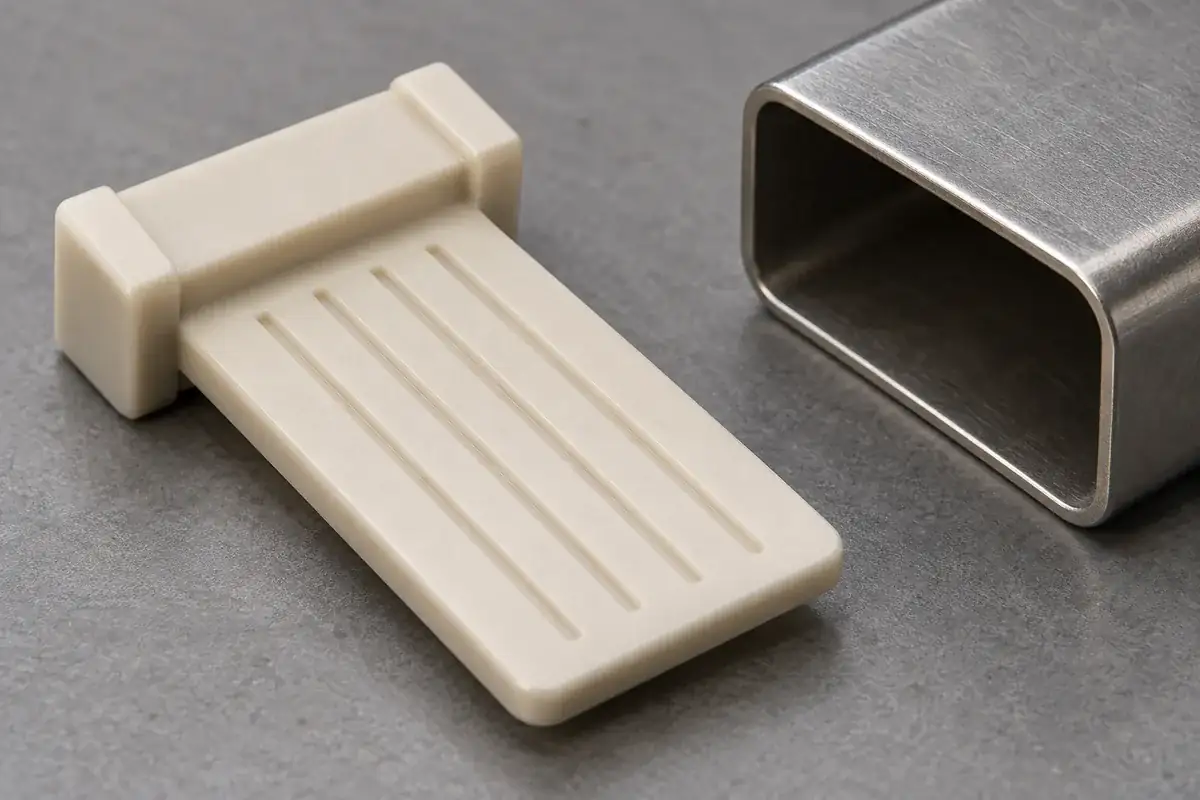
Review the whole insertion path
A final assembled model can show adequate clearance while missing an obstruction encountered on the way in. A retaining tab may pass a narrowed shell section before reaching its pocket. A rear shoulder may meet an edge before the tongue is fully guided. Review the motion in the intended direction and include the approach angle allowed by the assembly fixture.
Lead-ins help establish guidance, but their usefulness depends on the surfaces that meet them. A chamfer on the plastic cannot compensate for every shell edge condition, particularly if the carrier approaches at a large angle. Likewise, rounding an edge may change a retention function or reduce available engagement. Any geometry change should preserve the intended final location and retention.
Interference is not necessarily a defect when it is part of an approved retention design. The design must still specify where it acts and how the plastic accommodates it. An unintended interference on a thin tongue is a different condition from a controlled engagement at a robust retaining feature. Do not combine both into one unexplained assembly-force requirement.
The shell datum-stack review helps identify whether a carrier reaches its intended seat. A component that stops early may be reported as correctly retained even though the tongue position is wrong. Confirm seating at the intended reference surfaces before treating the completed insertion stroke as proof of correct assembly.
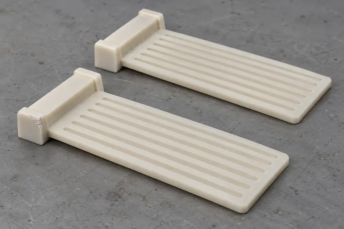
Support the carrier where the force belongs
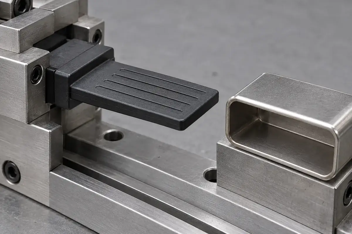
Assembly force should enter through geometry intended to receive it. Pushing on the thin tongue because it is accessible can bend the tongue or concentrate stress at its root. A rear support may be more appropriate where the design provides a sufficiently robust surface. The fixture must hold that region without obstructing the shell or distorting the carrier.
Alignment deserves the same attention as force magnitude. A fixture can apply a modest load along the wrong axis and still damage a delicate feature. The guides should establish the intended approach before the parts begin their critical engagement. Review clearance within the fixture itself, since excessive freedom can permit one corner to strike first.
A force-versus-displacement trace can be useful when the process supports it and the method is agreed. Changes in the trace may help locate initial contact or final seating. However, a peak value alone does not identify the cause, and no generic trace proves an acceptable USB assembly. Relate the observed events to the actual mechanical sequence and inspected part condition.
The ejection-control discussion uses the same load-path principle earlier in manufacturing. A carrier weakened during release may fail later under an otherwise reasonable installation load. That possibility is why pre-assembly inspection and controlled sample identity are valuable when assigning the source of damage.
Choose corrections that address the observed mechanism
If scraping follows a shell edge, inspect that edge and its relationship to the plastic path before proposing a tougher resin. If a corner crushes only in a poorly guided approach, correct the guidance and confirm the component geometry. If a crack follows a local molding weakness, investigate the flow and section there. The evidence should determine which part of the system changes.
Changing material can alter stiffness, shrinkage and the response of retention features as well as damage resistance. It therefore requires a review of the molded geometry and assembled behavior, not simply a substitution based on a single property. Keep the exact grade and its approval status connected to the revised samples and any required exposure evaluation.
Lubricants or assembly aids should not be introduced casually to hide unexplained resistance. They can change friction and leave residues that matter elsewhere in the connector. Where an aid is part of the intended process, its material compatibility, application and downstream effects need explicit review. The plastic component’s cleanliness requirement should remain visible in that decision.
After a correction, inspect both the final position and the condition of the plastic. A lower installation force is useful evidence only when the carrier still reaches its intended seat and retains the required geometry. Repeating the agreed check with controlled counterparts establishes whether the revised process addresses the original mechanism without creating a new interface problem.
For custom USB insulators and terminal carriers, provide the shell geometry, assembly direction and proposed support regions with the part drawing. Those inputs make it possible to review thin sections against the real installation sequence.
Damage prevention becomes more effective when the investigation follows contact, force and support through the assembly. That approach makes a scratch or crack useful evidence, rather than a reason to tighten unrelated dimensions or change material before the actual mechanism is understood.