
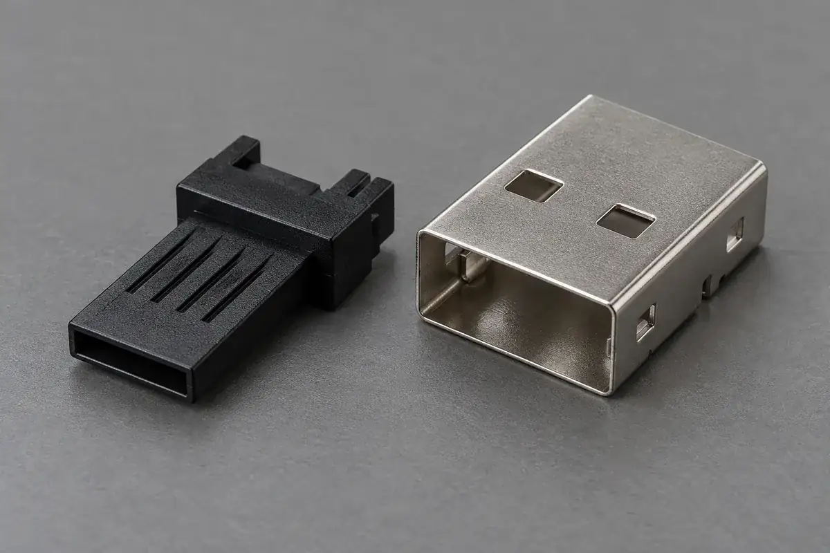
A USB connector can look like a small metal opening from outside an electronic product. Inside, several components establish the relationship between the mating interface, contacts and equipment. The molded insulator is one of those components. Buying that plastic part requires a different definition from selecting a complete connector from a catalog, even when both conversations begin with the same connector family name.
For a custom molding program, the useful starting point is the item that leaves the molding supplier. It may be an insulating tongue, a rear terminal carrier or a retaining piece assembled into a separate shell. Naming that item makes its dimensions, material and acceptance conditions concrete. It also helps the connector designer provide the surrounding geometry that the plastic supplier needs without confusing assembly responsibility.
Product design illustrations show the molded components and their assembly relationships.
Follow the plastic through the assembly
An insulating tongue provides physical separation and support around a defined contact arrangement. Its thin forward portion may enter the mating region while its thicker rear portion locates within the connector construction. The exact relationship depends on the approved design. A tongue can be molded separately and assembled later, or belong to a component that captures metal parts during molding.
A terminal carrier may instead perform most of its work behind the visible mating opening. It can establish contact installation paths, support retained sections or locate a subassembly relative to the shell. Calling both pieces a housing is understandable in conversation, but the manufacturing drawing should identify which surfaces position the contacts and which surfaces position the plastic itself.
A retaining piece is another distinct item. Its purpose might be to keep an insulating body seated or to support a later assembly operation. Its material and geometry must suit the actual loading and installation sequence. A visually similar plastic frame should not be treated as interchangeable simply because it fits within the same broad connector envelope.
Hirose’s CX connector documentation identifies insulating and metal components within a connector family. That component breakdown is useful context for discussing supply scope. The manufacturer’s complete-product specifications belong to its stated connector configuration; they do not become performance claims for a custom plastic piece illustrated elsewhere.
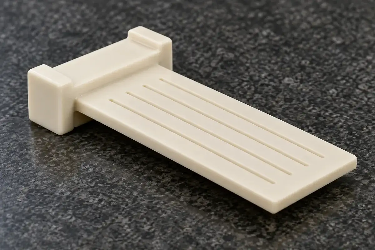
Use counterpart drawings to explain the function
The plastic drawing should show the dimensions and conditions being purchased. The counterpart drawings explain why those requirements exist. If a rear shoulder seats against a shell stop, the stop geometry helps identify the meaningful measurement direction. If a contact passes through a molded slot, its installation path can reveal an obstruction that is invisible in the final assembled view.
This does not mean every counterpart becomes part of the molding order. It means the design review has enough context to evaluate the plastic intelligently. A supplier can review a lead-in, parting line or gate location against the surrounding envelope without undertaking contact stamping, shell fabrication or complete connector assembly. The order should preserve that distinction in its deliverables.
Consider a carrier that meets its overall width but requires excessive force to enter a shell. The problem might be a local rib, a displaced locating shoulder, a shell edge or an insertion angle. An isolated width value cannot decide between those causes. Assembly drawings and a description of the intended support points allow investigation to focus on the interface that actually resists motion.
The same approach distinguishes this work from components molded around metal terminals. That manufacturing route requires control of the loaded metal inserts and their exposed regions. A separately molded USB insulator instead needs a defined later installation relationship. Either route may suit a design, but neither should be silently substituted during quotation.
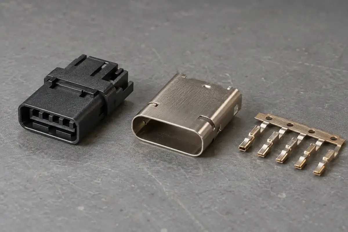
Keep performance evidence attached to the tested item
Plastic geometry can influence contact position, clearances and mechanical support. Those contributions matter, but they do not independently establish a complete connector’s signal performance or operating rating. Metal geometry, contact surfaces, shell construction and the rest of the assembly also participate. A successful plastic dimension report answers a narrower and valuable question: whether the inspected plastic meets its agreed definition.
Material documentation has a similarly specific role. An exact resin grade can establish the material being supplied and provide properties for engineering review. It cannot alone demonstrate that every thin rib, weld line or assembled interface will behave as intended. The application must connect the selected grade to the part geometry, molding condition and relevant exposure or loading.
The USB-IF Type-C information describes its specification and compliance program. Certification and logo permissions are managed within that framework. A custom molded insulating component should therefore be released to its own purchase specification while complete-product compliance remains attached to the responsible connector or equipment program.
This is useful commercially as well as technically. A plastic-part quotation can explicitly include tooling, trial samples, recurring molding, packing and agreed dimensional reports. The buyer can then compare proposals against the same manufactured item. Adding unspecified complete-connector claims would make the comparison less meaningful rather than make the plastic proposal more comprehensive.
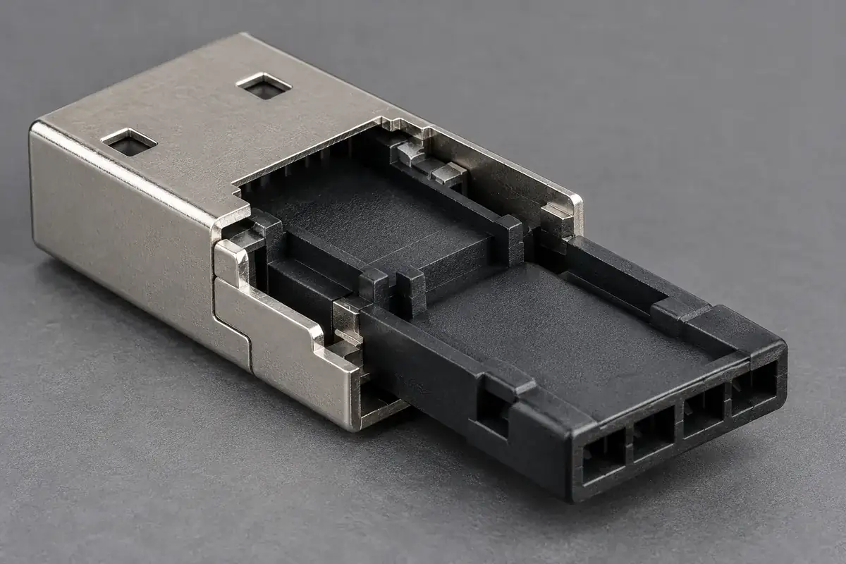
Release the part together with its interface revision
Interface changes often arrive through a counterpart revision. Moving a shell stop may change tongue position even when the plastic shape stays unchanged. Changing a contact retention section may change installation force while preserving the visible mating arrangement. A useful release record identifies the plastic revision and the counterpart revisions against which its relevant interfaces were reviewed.
The sample plan should distinguish free-part inspection from assembly evaluation. Free-part measurements can reveal molding variation, while a supported assembly check shows what happens under the intended constraints. Neither result should overwrite the other. If the shell intentionally locates a flexible region, record that support state rather than presenting a forced measurement as the unrestrained shape.
For a discussion of the plastic locating relationship, continue with the shell and insulator datum stack. It explains why a good local dimension may still leave the tongue displaced in the assembled opening. That question becomes much easier to answer after the purchased component and its functional references are clearly named.
A drawing package can leave some manufacturing choices open while holding the functional interfaces fixed. Gate design, cavity arrangement and inspection-fixture details may be developed during review. The important point is to identify which proposals need design approval before they change a locating surface, contact path or retention feature. That keeps manufacturing development connected to the assembly purpose.
Our custom USB connector insulators and terminal carriers scope covers drawing-defined plastic components. Share the part model with the mating geometry and assembly sequence so the molding review can focus on the tongue, carrier or retaining part you actually need.
The strongest component specification is not the longest list of connector claims. It is a clear account of the plastic’s function, the interfaces it must maintain and the evidence required to release it. From there, tooling and sample decisions can be made against the real assembly rather than an ambiguous product name.