
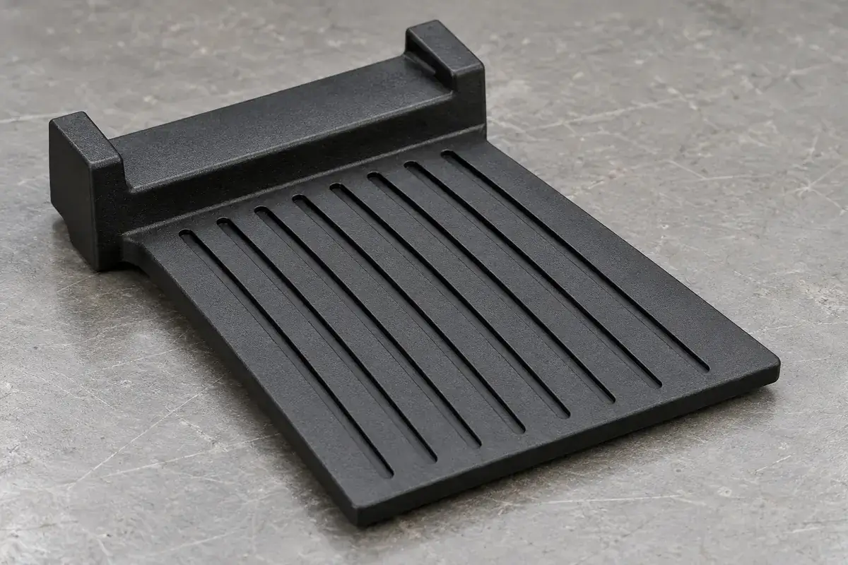
A thin lip of plastic at a contact-slot entrance can matter more to assembly than a much larger witness on an unused outside surface. The difference is the path of the terminal. A lip that projects into that path can catch an edge, change installation force or break away during assembly. Flash control therefore begins with the interface function, not a single cosmetic description applied to the entire part.
The challenge is to connect the observed lip with the steel surfaces that created it. Narrow slots and separating ribs put several molding features close together. An apparently simple obstruction may arise from a local shutoff, insert mismatch, tool wear or a process condition that reveals an existing gap. Removing the visible plastic does not by itself identify or correct that cause.
Product design illustrations show the molded components and their assembly relationships.
Distinguish extra material from missing material
Flash is material that has entered an unintended gap. A short-filled rib is missing material where the cavity should have filled. A torn slot edge may begin as complete geometry and become damaged during ejection or later handling. These defects can look similar in a distant photograph, yet they point toward different mechanisms and should not share a corrective action merely because all occur near a slot.
Use lighting and viewing directions that reveal whether the feature projects beyond the intended boundary. A top-down image can hide a lip folded along the slot wall. A low-angle view may show that projection, while backlighting can reveal an obstructed opening. The observation should describe location, direction and attachment, rather than use flash as a catch-all term for any rough-looking edge.
A terminal installation path is three-dimensional. The final slot width may appear adequate while the entry region contains an obstruction. Review the lead-in, the approach angle and any local changes in section. Where a gauge is proposed, verify that it represents the relevant interference instead of passing through a wider region that the real terminal does not use.
A small detached particle creates a different concern from an attached lip. Its later location is unpredictable, and finding a clean slot after assembly does not prove that the particle was absent beforehand. Preserve samples before trimming or cleaning during investigation. Otherwise, a useful clue to the molding interface may disappear before the tool is inspected.
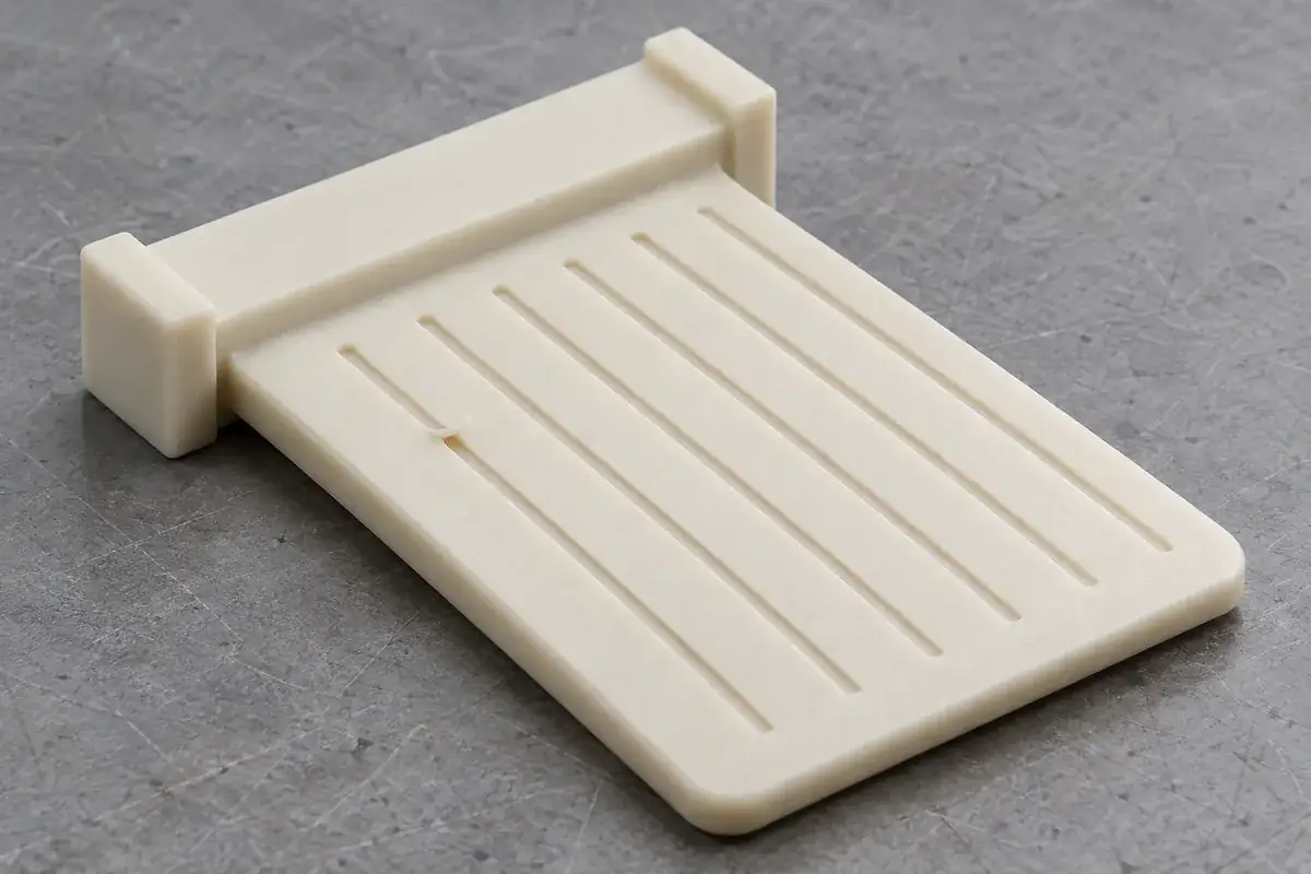
Map the defect to the tool interface
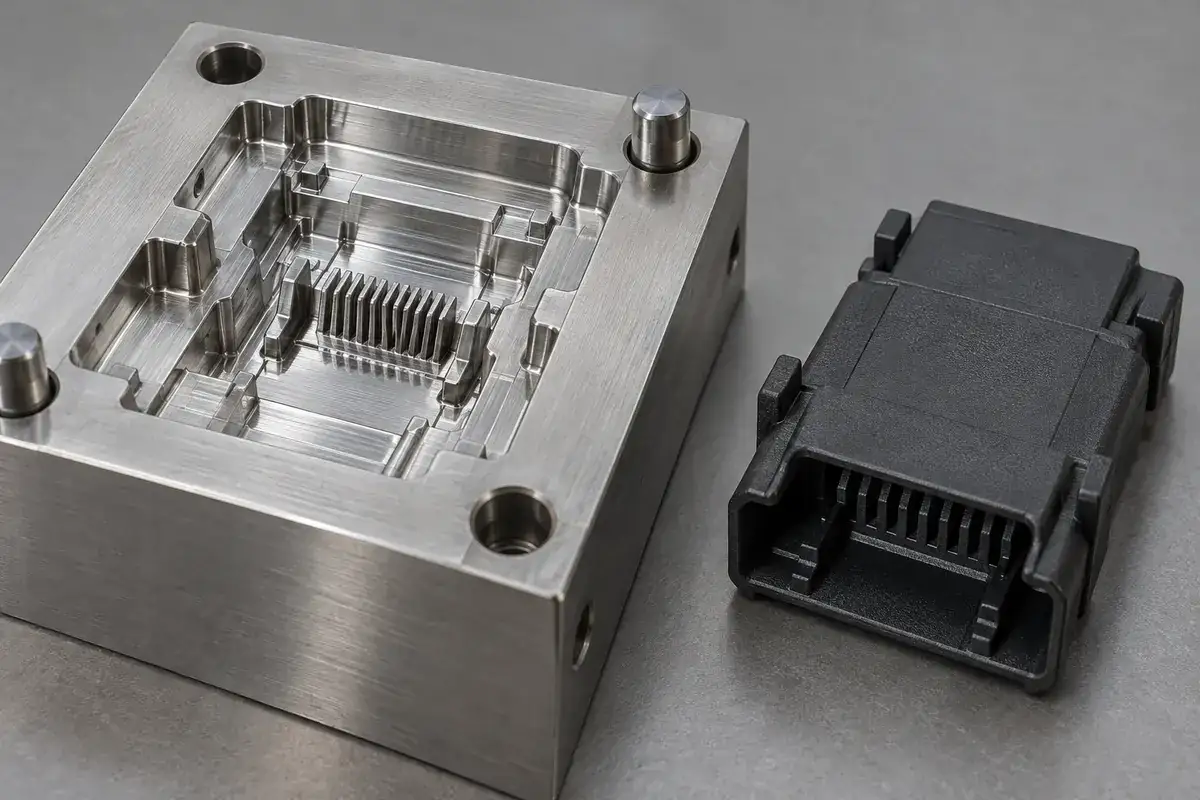
The tool drawing should show which steel surfaces form the slot walls, rib tips and entry region. When separate inserts meet near those features, their location and support help determine whether the joint stays closed during molding. A small unsupported feature can respond differently under load from the surrounding insert body, even if an unloaded tool inspection looks satisfactory.
A defect repeated at the same position in one cavity invites a localized investigation. Look for a damaged edge, mismatch or support condition corresponding to that position. A broad change across several cavities may suggest a shared process or mold condition. These patterns are clues rather than proofs, but preserving cavity identity makes the investigation more efficient than combining all rejected samples.
Changing injection conditions may reduce visible flash while also changing the filling of thin ribs. That trade-off should be evaluated directly. A process window that suppresses extra material by leaving a critical region incompletely filled is not a satisfactory correction. The objective is to fill the intended geometry while maintaining the tool interfaces that exclude polymer from unintended gaps.
For the steel-side questions, see precision connector mold inserts. That scope concerns the reusable forming components. The molded USB carrier remains the acceptance item for this discussion, so tool repair should be followed by evaluation of the resulting plastic features rather than treated as automatic product approval.
Specify an inspection that sees the functional edge
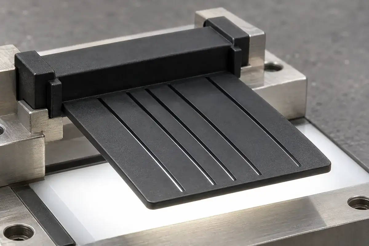
An inspection plan needs an agreed region and a useful view. Stating that the component must be flash-free without defining the inspected interface can lead to disagreement over harmless remote witnesses while missing an obstructed contact path. The drawing or acceptance document should identify where extra material is prohibited or limited and how the relevant condition is assessed.
Optical inspection can reveal small edges, but image threshold and focus can affect the apparent boundary. Keep lighting, magnification and part orientation consistent for a given method. Reference examples can help explain the intended decision where they are controlled and approved. They supplement the dimensional or functional definition rather than silently replace it with a subjective appearance preference.
A trial installation may reveal interference that is difficult to characterize optically, but it can also remove a fragile lip. Use a documented sequence that preserves pre-assembly evidence when needed. Compare the plastic observation with the installation behavior and any recovered debris. A successful insertion alone should not erase a known loose-particle or geometry issue.
The Hirose CX product family provides manufacturer context for insulating and contact components within an assembly. Its complete-connector specifications are not a flash limit for a custom molding. The applicable plastic acceptance value and method must come from the approved component and assembly requirements.
Treat trimming as a controlled process decision
Manual removal may appear attractive for early samples, especially when only a few openings are affected. However, a blade or abrasive can change the slot boundary, round a retention feature or leave particles. If trimming is part of the agreed production route, define its access, remaining geometry, cleaning and verification. If it is temporary development work, identify the samples accordingly.
A better investigation asks why the material appeared and whether the correction remains stable over the intended production conditions. That might involve repairing a steel edge, improving support, resolving insert location or adjusting an approved process. The appropriate action depends on the evidence. Raising a general acceptance threshold simply to accommodate an unexplained trend would leave the assembly mechanism unresolved.
Flash also connects to cleanliness and handling. A stable attached witness and a detachable sliver require different considerations. Keeping these observations separate helps the manufacturing team decide whether the main issue is cavity geometry, a secondary operation or transfer of debris after molding.
After a correction, compare identified samples from the relevant cavities using the same inspection conditions. Include the adjacent thin features so improved slot clearance is not achieved at the expense of rib completeness. Where a terminal or shell interface is involved, repeat the agreed assembly evaluation with the controlled counterpart revision.
For custom USB insulators and terminal carriers, provide the terminal path and critical slot regions with the plastic drawing. This allows the tooling proposal and sample plan to target the edges that matter to the assembly.
Flash control works best when the evidence travels from the observed plastic lip back to its forming interface, then forward again to the installed component. That chain distinguishes a lasting correction from a cosmetic cleanup and gives both supplier and buyer a repeatable basis for release.