
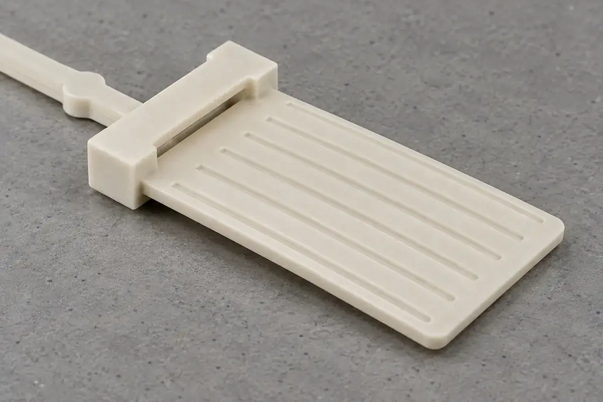
A weld line appears where separated melt fronts meet during injection molding. In a USB insulating tongue or rear carrier, the flow can divide around local obstacles and rejoin near a narrow bridge. The visible line may be subtle, while its location relative to the load path can be important. Appearance alone is therefore an incomplete basis for deciding whether the feature is acceptable.
The engineering task is to understand why the fronts meet there and what the surrounding plastic must do during ejection, contact installation and shell assembly. That connects a molding observation to the actual component function. It also prevents a broad material-strength value from being applied uncritically to a local region formed by a particular flow history.
Product design illustrations show the molded components and their assembly relationships.
Trace the split and reunion of the flow
A core feature, opening or local thickness arrangement can divide the incoming polymer. The streams then travel different paths before meeting. Their condition at reunion depends on the geometry, material and molding process. Mapping those paths is more informative than marking a line on the finished sample without identifying the obstruction or gate arrangement that created it.
A tongue may also contain repeated channels and a thicker rear carrier that influence how the thin front fills. The nominal flow direction from the gate does not guarantee that every small region fills along a simple straight path. Review the detailed section transitions and consider whether one route advances ahead of another around a local feature.
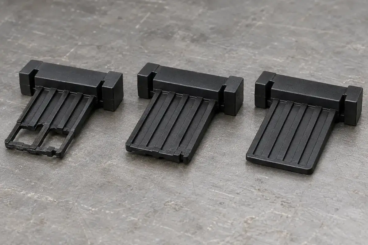
Short-shot studies can help reveal the filling sequence during development when planned appropriately. Each specimen represents a deliberately incomplete fill and should be identified as such. The sequence provides evidence about progression through the cavity; it is not a set of acceptable production parts or a direct measurement of weld-line strength.
Celanese’s Vectra LCP technical guide addresses design and molding for that polymer family. Consult grade-specific guidance when evaluating a candidate material. The local behavior of a weld region still needs consideration in the actual molded configuration rather than inference from the family name.
Relate the line to the mechanical job
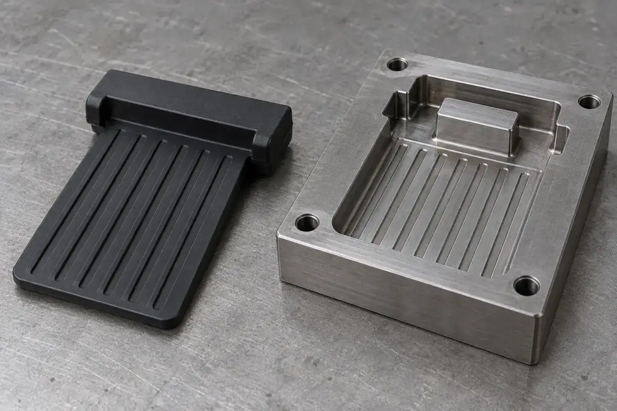
The critical question is where force travels through the component. A rear bridge may carry load during terminal installation or react the motion of a retaining feature. A tongue root may bend when the assembly is guided into a shell. If a meeting region lies across that load path, it deserves attention even when its surface appearance is unobtrusive.
A line in a lightly loaded region can present a different concern from a similar line across a narrow retaining root. That does not justify a universal acceptable location; it means the design review should identify the relevant loading and geometry. The same molded feature can experience different forces under alternative assembly sequences, so include the intended process in the evaluation.
Material data from a conventional test specimen describes its stated specimen and test conditions. It should not be treated as the measured strength of a thin bridge with a weld line in another molding. The gap is especially important when directionality or reinforcement affects the local response. Use the data for selection and analysis, then define the application evidence needed.
The shell-assembly damage guide explains how force can enter a carrier away from the point where a crack appears. Combining that load-path review with the flow map helps decide whether the priority is a gate change, a section revision, an assembly-support improvement or more than one of those actions.
Compare changes without hiding their trade-offs
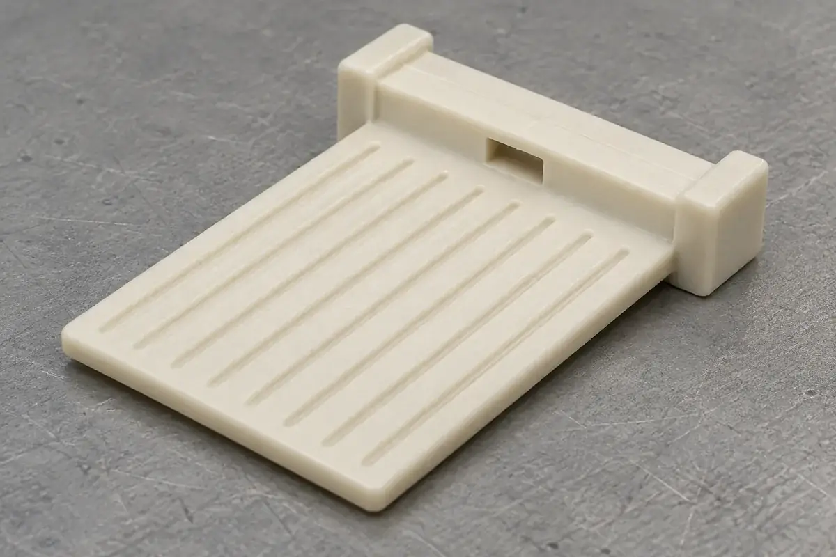
Moving the gate can relocate the meeting region, but it also changes the remaining gate witness and the route into the tongue. A proposal should therefore include the new assembly clearance and trimming requirements. The gate-vestige guide covers those consequences, which are easy to miss when the trial focuses only on eliminating a visible line.
Changing a local wall or opening can alter the flow split and the structural section at the same time. That may be useful, but the two effects should be understood separately. A thicker bridge may carry load differently while also changing filling and cooling. Review its relationship to adjacent slots and shell clearance before accepting the modification.
Process adjustments can influence how fronts meet, within the limits of the selected material and equipment. They should be evaluated as part of a controlled molding condition. A setting that improves one sample’s appearance does not prove a stable result, especially if it creates flash, changes dimensions or moves another defect to a less visible region.
Flow analysis can help compare alternatives before cutting steel, provided its material inputs and geometry represent the intended design. Treat the predicted meeting region as a development aid. Sample observations and the agreed component evaluations are still needed to confirm what the actual tool and process produce.
Plan evidence for the actual component
Define the relevant evaluation before selecting a test fixture. A fixture intended to compare bridge behavior should load the region in a way related to its application or clearly state that it is a development comparison. An arbitrary bend until break may rank samples, but without a defined method it cannot supply an application acceptance claim.
Keep the sample’s cavity, material grade, gate configuration and process condition connected to the result. If exposure or conditioning is relevant to the intended assembly, identify that state as well. A result detached from those details is difficult to reproduce and may not apply after a later tooling or material change.
Visual inspection remains useful for locating lines and finding associated incomplete fill, discoloration or surface disturbance. It does not alone establish local mechanical behavior. Conversely, a satisfactory component test does not remove the need to control the process features on which the result depends. The release plan should explain how development evidence relates to recurring production checks.
Where a change moves the line away from one critical region, inspect the new meeting region and the rest of the tongue. A defect has not been resolved merely because it is no longer visible in the original photograph. The comparison should cover the intended geometry, assembly relationship and any agreed loading evaluation under the revised configuration.
For custom molded USB tongues and carriers, share the intended assembly sequence and loaded regions with the plastic model. That lets the flow and tooling discussion focus on where a meeting front could matter to the component’s job.
Weld-line review is most useful when it links the gate, the local flow history and the force path through the finished part. This creates a defensible reason for a geometry or process change and a clear basis for evaluating the resulting samples without borrowing unsupported performance from a material datasheet.