
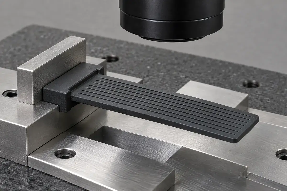
A dimensional report becomes useful when its measurements can be connected to the component’s function and reproduced on later samples. For a USB insulating tongue, that means more than listing overall length, width and thickness. The location of the tongue relative to the carrier, the state of narrow channels and the condition of assembly seats may explain fit more directly than a long list of convenient dimensions.
Release planning should begin while the drawing and tooling decisions are still open. The team needs to know what will be measured, in which state and from which references. It also needs to distinguish plastic-component acceptance from complete-connector evaluation. Those decisions make the first sample review informative instead of turning it into a debate over what an unexplained pass actually means.
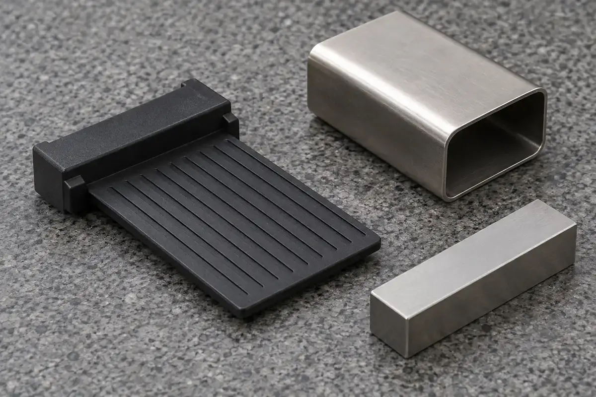
Product design illustrations show the molded components and their assembly relationships.
Organize dimensions around the locating chain
Start with the surfaces that position the carrier in its shell or receiving assembly. Then connect the tongue and contact-guiding features to those surfaces. This creates a measurement plan that follows the actual datum chain. An overall size remains useful where required, but it should not substitute for the location of a functional region relative to its assembly reference.
Separate local feature size from pattern location. A row of channels can have acceptable individual widths while the entire row is shifted relative to the carrier. Similarly, a tongue can have the intended thickness while its center region is displaced. Reporting both relationships allows the designer to see whether the issue concerns the feature itself or its placement.
The shell and insulator datum guide explains how seats and stops determine the assembled position. Use that chain to select meaningful measurement references. Where the drawing uses a different datum for a justified reason, document the relationship rather than assuming that a convenient fixture surface is functionally equivalent.
Include surface conditions that can alter contact at a datum. A raised gate witness, ejector mismatch or local debris can change seating without changing the nominal dimensions elsewhere. Those conditions may need a separate observation or envelope check. Their significance should be linked to the affected locating region instead of buried in a general appearance note.
Specify the sample state and measurement method
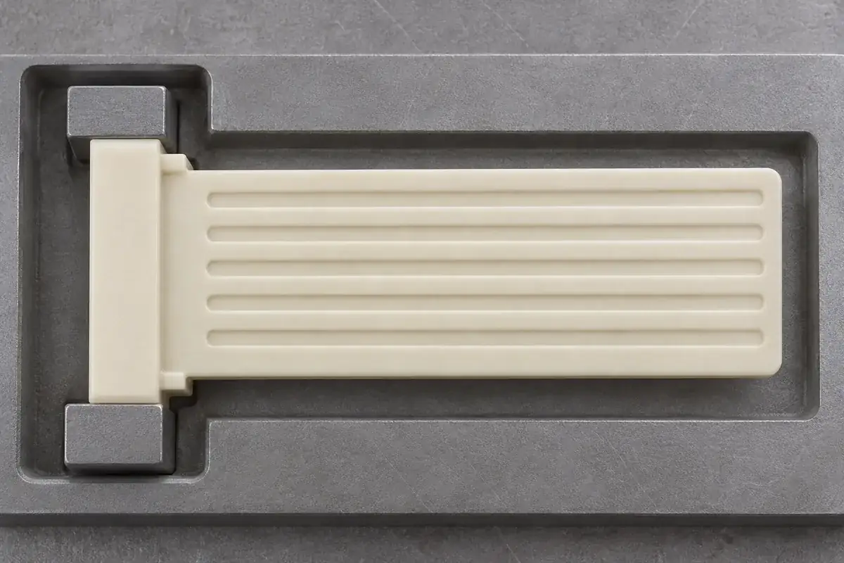
A thin plastic component can respond to support and clamp force. Define whether each requirement applies to a free part or a specified restrained state. A fixture that forces the tongue flat can produce a repeatable result while measuring a different condition from the one intended. Repeatability alone is not enough when the method answers the wrong geometric question.
The tongue flatness guide discusses that issue in detail. For release, carry the chosen support state into the measurement instruction. Identify contact points and any relevant loading so a second inspector can reproduce the arrangement without relying on the first inspector’s judgment.
Optical methods need controlled lighting, focus and feature-selection rules. Narrow dark channels and reflective neighboring metal can complicate edge detection. Contact methods require suitable access and an assessment of probe loading. The method should be demonstrated on the actual feature rather than selected only because an instrument can display more decimal places.
State the relevant timing, conditioning and exposure of the samples. A post-exposure requirement should not be represented by an as-molded measurement, and a warm sample should not be compared uncritically with a conditioned one. The exact state belongs to the agreed plan; there is no universal waiting period that can be assigned to every USB plastic component.
Preserve cavity and revision information
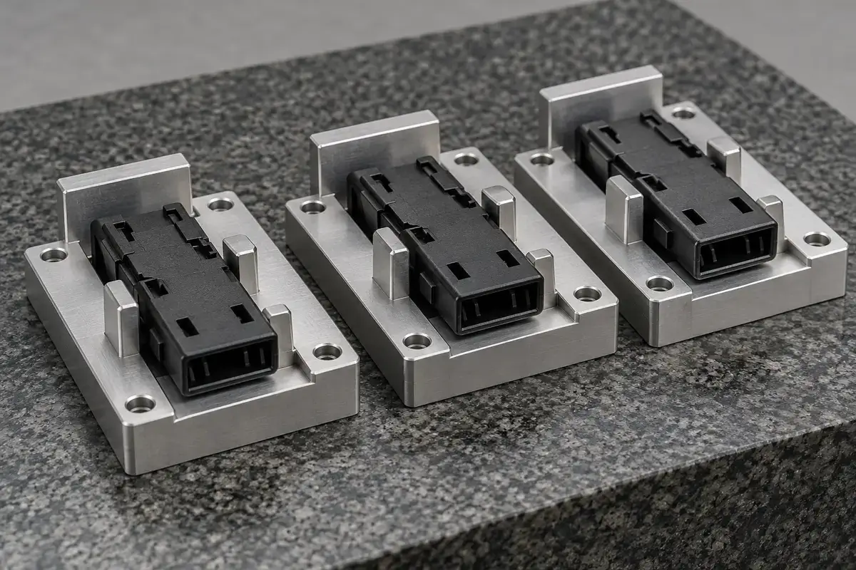
A multi-cavity tool can produce a repeatable difference associated with one cavity. Reporting only a pooled average can make that difference disappear. Keep the required cavity identity attached to samples and results so the tooling team can inspect the corresponding forming surfaces, support and process observations when a pattern emerges.
The sample record should also identify the plastic revision, exact material grade and relevant tooling configuration. A gate relocation or insert adjustment may change the result without changing the broad product description. If those changes are not recorded, an apparently inconsistent measurement history may actually combine several different configurations.
Counterpart revisions matter when an assembly check accompanies the dimensional report. A carrier tested with a revised shell is not necessarily comparable with an earlier sample tested in another shell. Record the counterpart used and the purpose of the check. This keeps component measurements and assembly observations connected without treating them as the same evidence.
Measurement uncertainty and method capability should be considered in relation to the requirement. A nominally precise instrument does not eliminate fixture variation, edge-selection effects or sample flexibility. Where the method cannot reliably distinguish the intended acceptance boundary, resolve the method or requirement before using its output as an authoritative release decision.
Make release a defined decision with evidence
A dimensional pass establishes conformity only for the features, samples and conditions evaluated. A functional fit check can provide additional evidence about the intended assembly. Neither should be described as a complete USB performance qualification. The USB-IF cable and connector program concerns defined complete-product certification within its own scope.
For the plastic component, list unresolved requirements explicitly and identify how they will be closed. A trial can support further tooling work without being production approval. A conditional release can exist where the buyer authorizes a defined condition, but it should state the affected scope. Avoid converting an incomplete report into approval by leaving its missing items unmentioned.
Once the configuration is accepted, connect the recurring inspection plan to the development evidence. Not every development measurement must necessarily repeat at the same frequency, but changes should be justified by the agreed control strategy and risk of the features involved. A reduced check should preserve the ability to detect the relevant variation rather than simply shorten the report.
Define which later changes require review. Material substitution, tool repair near a locating feature, gate movement and a revised counterpart can affect different parts of the evidence. The response should be proportionate to the change, but the decision must be visible. An approved sample is a reference to a configuration, not a permanent approval of every future part with the same name.
For custom USB connector insulators and carriers, send the critical feature list, datum scheme, required sample state and report expectations with the drawing. These inputs let tooling and inspection development support the same release decision from the outset.
A useful dimensional release turns measurements into traceable evidence about a defined plastic component. It preserves the difference between shape, location and assembly behavior, making future variation easier to investigate and later changes easier to review against the requirements that actually matter.