
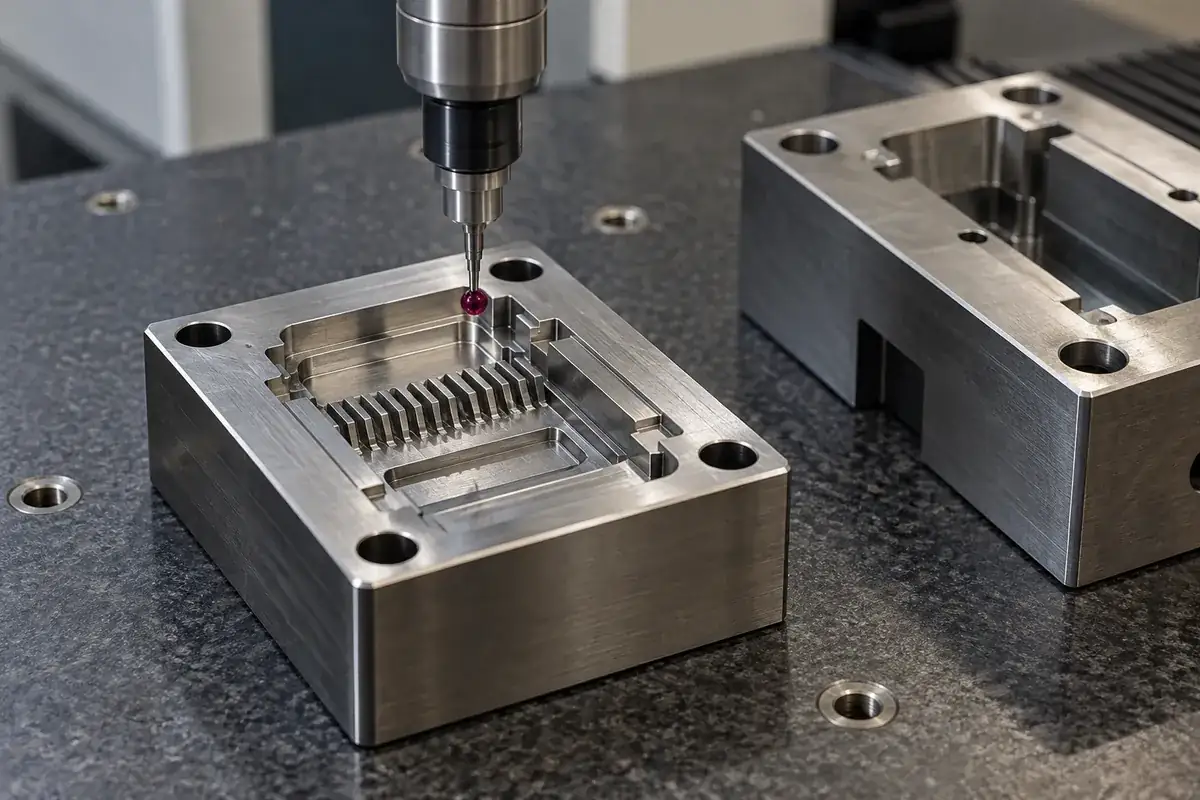
A connector mold insert can have an accurate cavity profile and still locate incorrectly in its mold plate. The cavity is only one part of the component. Its position depends on the faces, shoulders and locating features that seat the steel in the tool. Inspecting the attractive detail first, while treating the mounting envelope as routine, can leave the most consequential relationship untested.
Consider a replaceable insert that forms a row of small connector windows. A profile report aligned directly to that row may show very little deviation. Yet the row could be displaced relative to the insert's seating shoulder. Once the shoulder determines the installed position, the mismatch appears at the opposing core or parting surface. The measurement was useful, but it answered a different question.
Product design illustrations accompany the tooling and manufacturing explanations below.
Begin with the interfaces that locate the steel
The inspection plan should distinguish a locating face from a convenient surface. A broad underside might carry the primary seating function, a long side might establish orientation, and an end face might control longitudinal position. That is an example, not a mandatory datum scheme. The released tooling drawing must identify which relationships actually establish the insert in this particular mold assembly.
A fastening screw does not automatically provide the same locating function as a fitted key, shoulder or dowel. Its clearance may allow movement before the insert is tightened. Conversely, assuming that every surrounding surface locates the component can create an overconstrained interpretation that the assembly never intended. Read the fastening and locating details together before deciding how the part will be held for inspection.
Renishaw's FixtureBuilder guidance explains the familiar three-two-one support principle for stable, repeatable fixturing. This is a useful starting point for a rectangular insert. The fixture must still suit the drawing, mass, accessible faces and delicate features; a generic fixture diagram is not a substitute for the component's datum definition.
Preserve the relationship between seat and working geometry
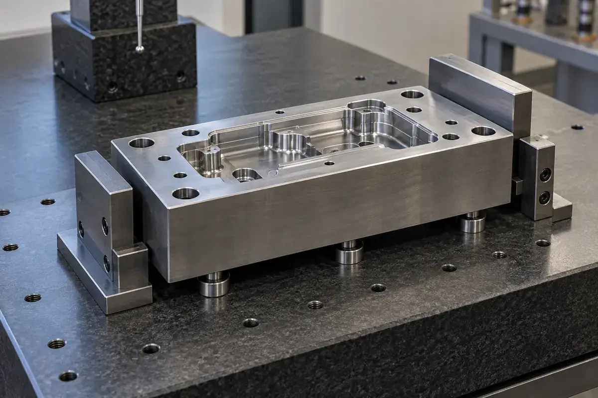
Inspect the mounting envelope and working features in a connected coordinate system wherever practical. That means retaining the relationship between the seat, cavity depth, core locations and parting face. Independent measurements can all be correct while failing to establish that relationship. A report containing separate dimensions needs enough information to show how those dimensions were referenced and how they combine in the assembled tool.
Best-fit alignment is useful when investigating shape, machining stock or a complex surface. It can also redistribute a positional discrepancy across the measured profile. If the acceptance requirement is tied to functional datums, a best-fit result should not silently replace that assessment. Keep diagnostic comparisons identified as such, and report the drawing-based evaluation separately so a visually reassuring color plot does not hide a seating error.
Temperature and part condition belong in the setup description. An insert brought directly from machining or cleaning may not be in a stable measurement condition. Coolant, protective oil or a small burr on the seat can also change the result. The aim is a repeatable state appropriate to the tolerances being inspected, rather than an elaborate report assembled from measurements taken under unrelated conditions.
ZEISS discusses this wider measurement system in its guidance on reducing CMM inspection uncertainty. The practical point is that a machine specification alone does not establish uncertainty for a narrow steel feature. Fixturing, alignment, probe qualification, environment and sampling strategy all belong in the decision about whether a measurement can resolve the requirement.
Choose measurement access before the features become inaccessible
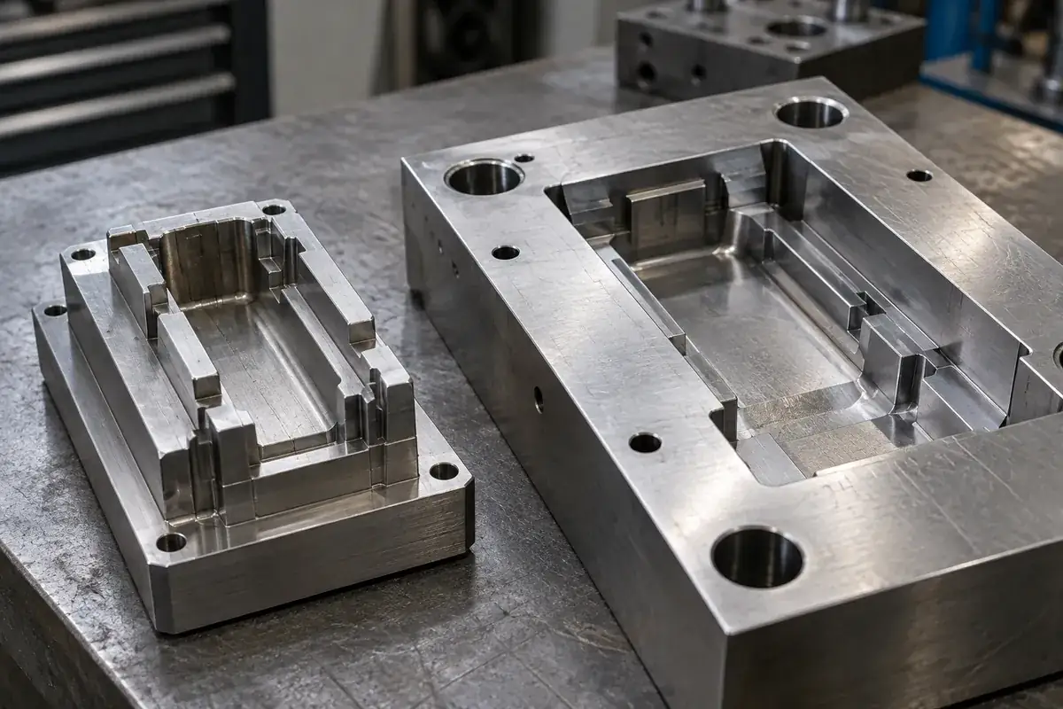
Fine ribs and deep slots create access problems that cannot always be solved with a smaller probe. The probe must approach the correct surface without striking adjacent steel, and the contact geometry must suit the feature being evaluated. Optical inspection can help with exposed edges and profiles, while other requirements may need tactile measurement or a dedicated method. Decide this before accepting a feature that no agreed method can inspect.
Separating an insert from its assembly can improve access, but it changes the state being measured. A loose steel component may meet its drawing while a pocket, backing plate or fastening arrangement introduces an assembly problem. Record which results describe the free component and which describe the assembled tool. Both can be necessary, and neither should be presented as a complete substitute for the other.
When two measurement methods disagree, first compare their definitions. An optical edge threshold and a tactile contact can respond differently to a small edge radius, texture or local burr. Repeating the same measurement more often will not resolve a difference in what is being measured. Review the feature, filtering, reference construction and acceptance rule before deciding that one instrument has identified a machining defect.
Surface finishing is another reason to plan inspection stages. Polishing a cavity wall after dimensional approval may change an edge or local profile. A coating can change a fit if its location and allowance were not included. The companion article on connector insert surface finish explains why a finished appearance must be assessed together with the steel geometry.
Make the fit check answer a defined question
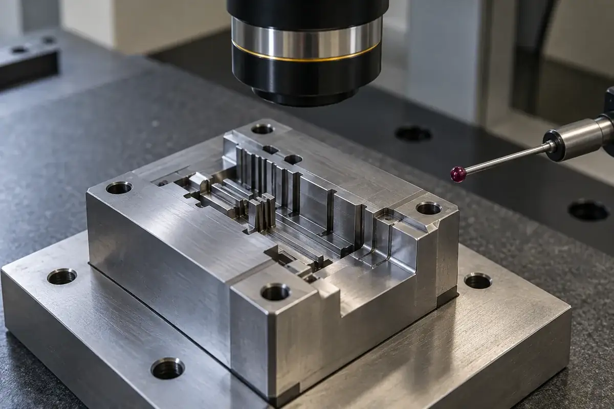
A trial fit should establish more than whether the insert can be pushed into the pocket. Check its seating, intended contact surfaces, orientation, retention and clearance to neighboring components. Do not use fastening force to conceal an obstruction. If assembly requires an unplanned correction, capture the change and its effect on the released dimensions rather than treating the resulting fit as proof that the original drawing was satisfied.
It helps to separate three conclusions: the insert meets its steel drawing, the insert fits the nominated mold assembly, and the assembled tool produces acceptable samples under the agreed trial conditions. These are related conclusions with different evidence. A fit check does not establish molded connector performance, while a favorable sample does not explain whether an individually fitted spare will work in the same pocket.
For a replacement program, preserve the measurement setup and mating-pocket identity with the approved insert revision. That record becomes particularly valuable when assessing spare insert interchangeability. Otherwise, a later supplier may reproduce the nominal cavity successfully while missing the seating relationship that made the original component usable in that specific tool.
Our review of precision connector mold inserts connects the working geometry with its mounting, finishing and inspection requirements. For a component order, the precision mold component service provides the scope for reviewing the insert drawing and its assembly interfaces. Agreeing those references early gives the steel inspection a clear purpose and makes subsequent fitting or trial decisions easier to explain.