
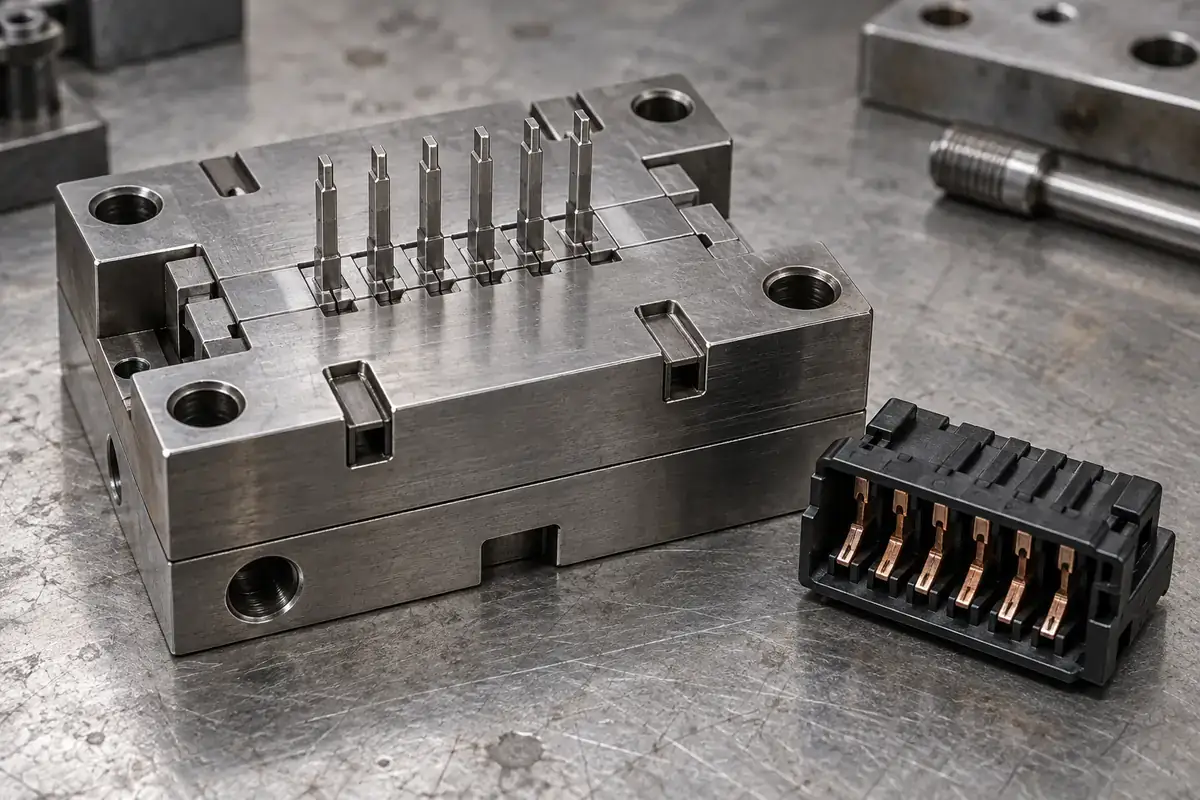
“We need a connector insert” can describe two very different purchases. One is a precision steel component installed in an injection mold. Another is a metal terminal placed inside that mold and captured in the plastic product. Confusing the two can produce a quotation that looks detailed while covering the wrong manufactured item.
The distinction becomes clearer when you follow the molding cycle. The steel mold insert stays with the tool and shapes successive parts. The molded-in terminal leaves with each finished component. Both can be small, metallic and dimensionally important, but they have different functions, drawings, quantities and acceptance conditions.
Product design illustrations accompany the tooling and manufacturing explanations below.
Ask what remains in the mold
A mold insert is a separately manufactured part of the tooling. It may form a cavity wall, a row of contact openings, a local shutoff or another defined portion of the plastic geometry. Its outside surfaces locate it in a holder; its working surfaces help establish the shape that polymer takes during molding.
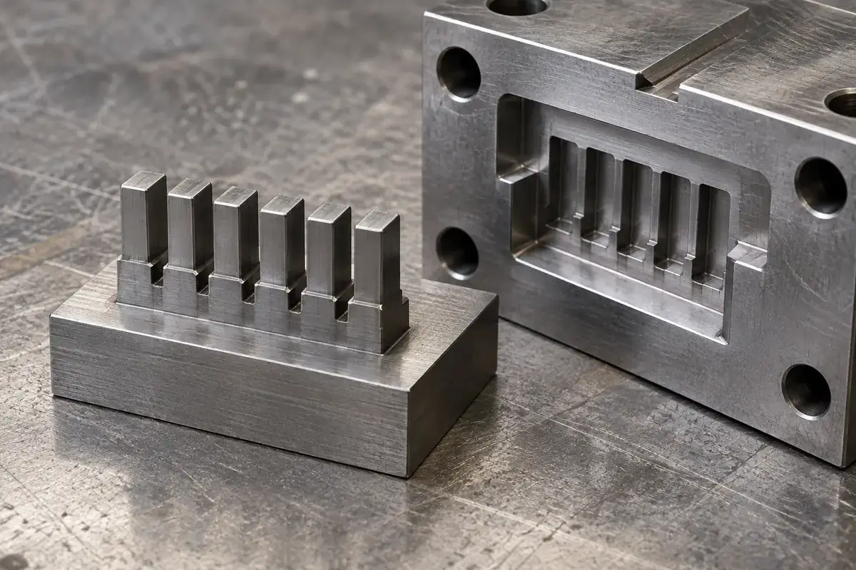
For an illustrative connector housing, a steel comb might form several narrow internal openings. The comb requires support, a controlled relationship to adjacent tool components and a workable release direction. It is not supplied as part of the connector assembly. Its job is to reproduce the intended feature repeatedly while remaining serviceable within the mold.
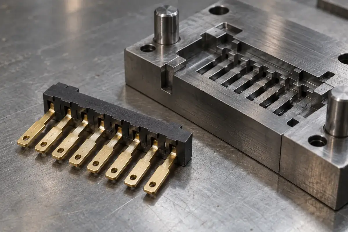
A molded-in insert is different. A stamped terminal, threaded component or other preformed item is loaded before injection and becomes part of the molded product. In a connector module, plastic may capture the terminal’s retained section while leaving its mating and termination regions exposed. The terminal’s material and surface condition belong to the product definition.
Autodesk’s explanation of insert types makes this distinction explicitly: part inserts leave with the molding, while mold inserts belong to the tooling. Its terminology is useful even outside simulation because it prevents two different physical boundaries from being represented by the same unexplained word.
The two interfaces require different drawings
The steel component has an interface with the mold holder. Its seating faces, retention arrangement and working geometry must relate to the rest of the tool. A drawing that shows only the connector’s plastic outline does not define how a replacement steel insert will fit an existing pocket or meet its neighboring tool surfaces.
The terminal has an interface with the molded plastic and with the eventual connector assembly. Its location, plating restrictions and required exposed areas matter during molding. However, a terminal drawing does not normally define the supporting mold steel, the cavity pocket or the insert’s attachment method. Those are additional tooling decisions rather than missing dimensions to invent on the terminal print.
A third use of “insert” sometimes refers to a separately molded insulating piece assembled into a connector shell. That component is neither a reusable steel tool insert nor necessarily a metal part captured during molding. Name it as an insulating body or connector module, then state its assembly relationship. This avoids ambiguity when several suppliers contribute different parts of one connector.
Our comparison of insert molding and contact assembly follows that product-side sequence. It explains why a terminal may be captured during molding or installed afterward. The present distinction concerns the tooling component itself: the item that forms the plastic, rather than the item retained by it.
Precision belongs to a defined relationship
A finely machined steel feature is important, but its measurement is not automatically the tolerance of the finished connector. The plastic also responds to filling, cooling, material condition and release. In a terminal-bearing component, insert position and later carrier removal can introduce further relationships. Tool inspection and product inspection therefore answer connected but separate questions.
Suppose a replacement comb insert fits its holder correctly but its working blades sit differently relative to the tool datum. The holder fit alone would not establish the intended contact-opening positions. Conversely, a correctly manufactured insert cannot prove that a particular molding process produces an acceptable connector. Keep each measurement attached to the physical item and state that it describes.
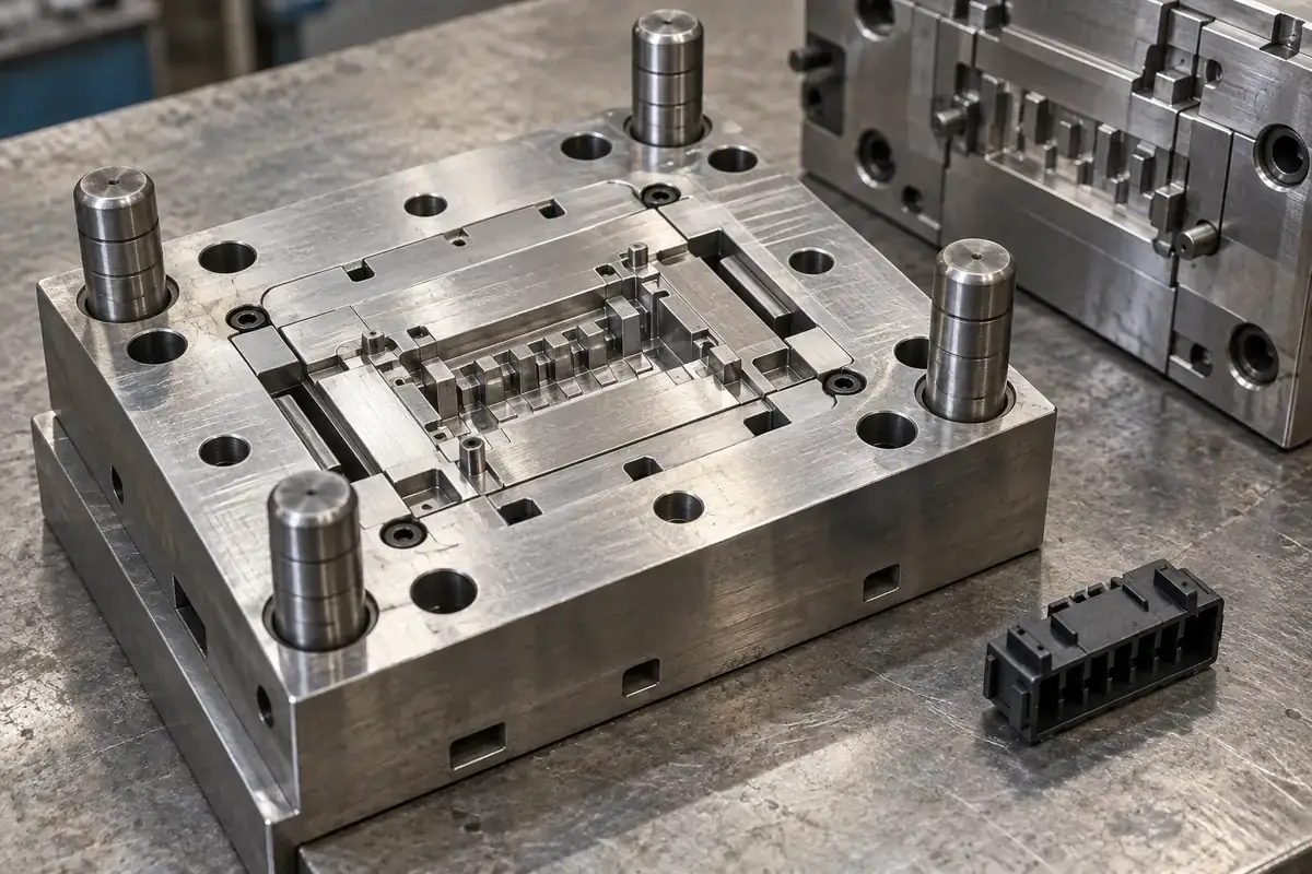
This separation also affects quantities. A mold may need one working insert and a planned spare, while production consumes a new set of terminals in every molded component. A quotation should distinguish tool components, development work and recurring product supply. Otherwise, a low unit price can conceal that the quoted unit is not the one the buyer expects.
Ownership and maintenance similarly follow the object. A steel insert may require a revision-controlled spare drawing and a defined replacement procedure. The terminal supply needs its own material and lot controls. Neither arrangement can be inferred from an order line that says only “precision connector inserts,” regardless of how familiar that phrase sounds.
Replacement is a tooling operation
Replacing a steel insert can restore a worn feature or introduce an approved geometry change without replacing the complete mold. That possibility depends on the tool’s construction. A removable component still needs suitable access, registration and support. Its replacement must preserve the surrounding interfaces and return the tool to the intended assembled condition.
Not every small region benefits from being divided into a separate component. Additional interfaces can complicate alignment, thermal behavior and maintenance. The guide to replaceable inserts in connector molds considers those trade-offs. The objective is a useful repair or adjustment route, rather than making the tooling modular simply because modularity sounds desirable.
When discussing precision connector mold inserts, identify the supplied steel component, its holder interface and the plastic feature it forms. If the required deliverable is instead a finished terminal module, use the insert-molded connector component scope. Clear naming gives both discussions a much more reliable starting point.
A short review of the manufacturing sequence usually resolves the ambiguity: what enters the machine, what stays in the mold and what leaves with the part? Once those objects are named, their drawings and acceptance criteria become easier to separate. That is the foundation for a meaningful tooling quotation and a useful technical conversation.