
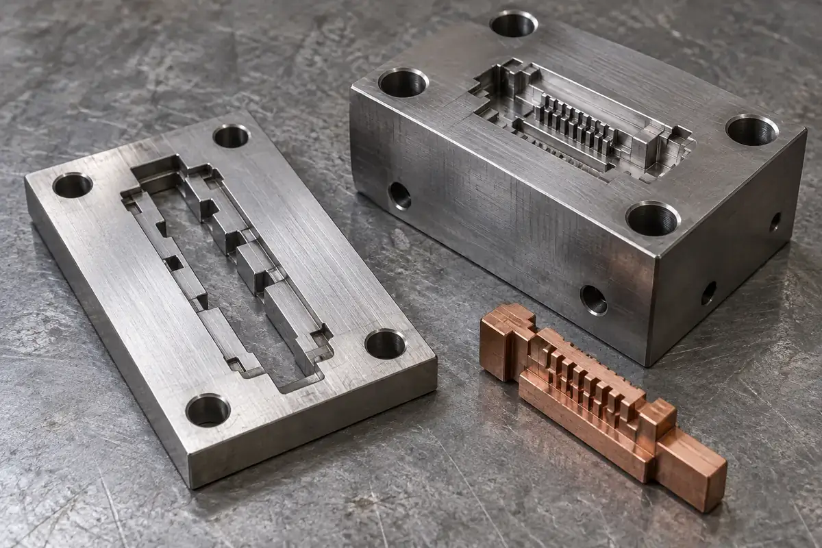
Product design illustrations accompany the tooling and manufacturing explanations below.
A connector mold insert can contain a row of narrow through-slots, a blind pocket and several ground locating faces. Calling the whole component an “EDM part” hides the decisions that make those features possible. Different surfaces may need different machining routes, and the most important distinction is often where the cutting electrode can physically travel.
Wire EDM and sinker EDM both remove electrically conductive material by controlled electrical discharges. They do not, however, offer the same access. The choice should begin with the section through the required steel geometry. A route that produces a profile efficiently from one direction may be unable to reach the bottom of an enclosed recess.
Follow the electrode through the feature
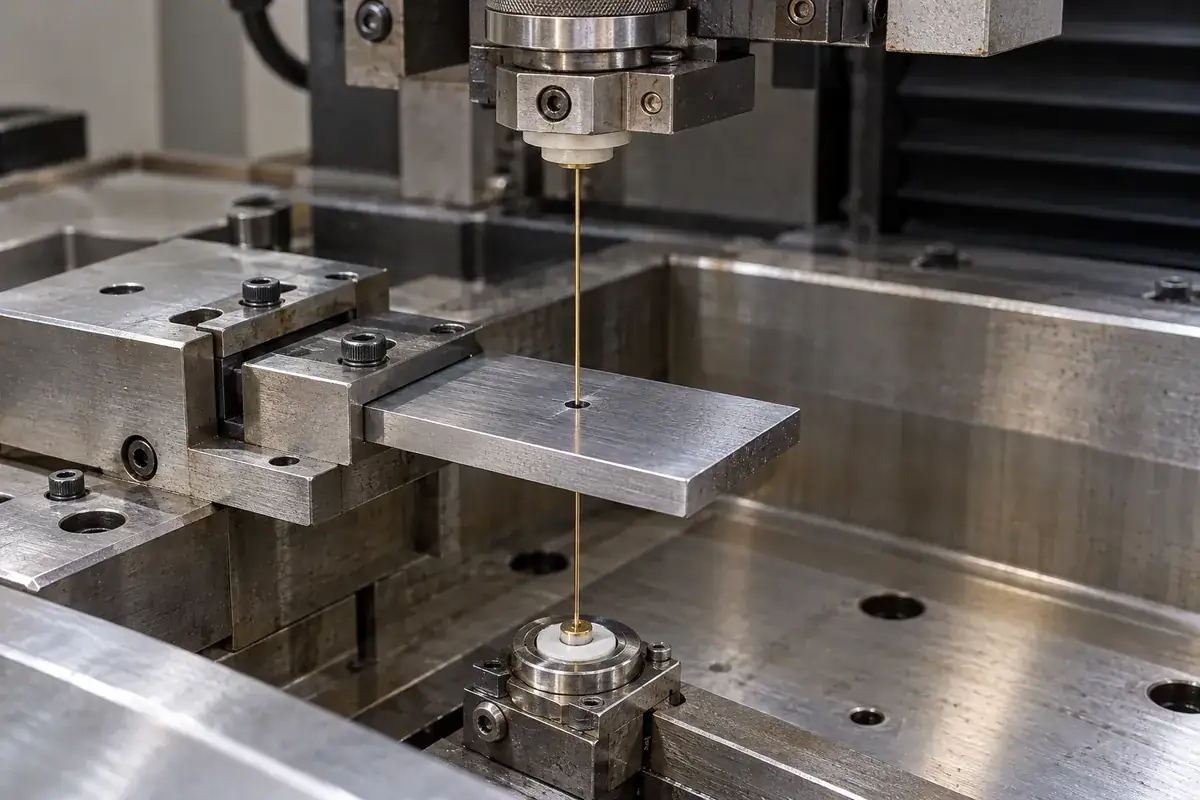
In wire EDM, a continuously supplied wire follows a programmed path through the workpiece. A through-profile is a natural candidate because the wire can extend through the material between its guides. For an enclosed internal profile, the setup needs a practical way to introduce the wire, normally through a prepared starting hole. The starting arrangement is part of the manufacturing plan.
Imagine a flat connector core segment with several narrow slots running completely through its thickness. Wire access may be straightforward before that segment is assembled into the mold. The same features could become inaccessible after assembly, or a retaining shoulder might obstruct a guide. This is why machining sequence and assembled geometry must be considered together.
A blind cavity is different. Its floor must remain in the steel, so an ordinary through-cutting path cannot simply continue through it. Sinker EDM uses a shaped electrode that approaches the workpiece and forms the accessible recess. MicroGroup’s EDM process description explains the conductive workpiece, dielectric environment and shaped-electrode principle behind this route.
The electrode still needs access. A deep recess with an overhanging roof is not automatically manufacturable merely because sinker EDM can make blind features. The proposed electrode must be made, positioned, moved and removed. Some geometries need a different split in the tool, several electrodes or another construction entirely. Access problems do not disappear when the cutter becomes an electrode.
Small features still have physical limits
A drawing can show a perfectly sharp internal corner, while the chosen manufacturing process leaves a finite radius. Wire size and discharge clearance affect the profile that wire EDM can produce. In sinker EDM, the electrode geometry and the discharge gap also matter. The correct response is to define the functional corner and an achievable relief, rather than promise mathematically sharp steel.
Connector features often sit close together, which makes the remaining steel just as important as the empty space. A narrow slot may leave a slender blade on either side. Those blades must survive manufacturing, handling and molding. An approach that produces the slot but leaves fragile, unsupported steel has not solved the tooling problem.
Workholding deserves attention even though EDM does not impose the same conventional cutting loads as milling. The insert must retain its position as material is removed, and thin sections must be protected during handling and subsequent finishing. Makino’s EDM overview distinguishes wire and sinker applications; it is a useful process reference, not a guarantee of the dimensions of a particular finished insert.
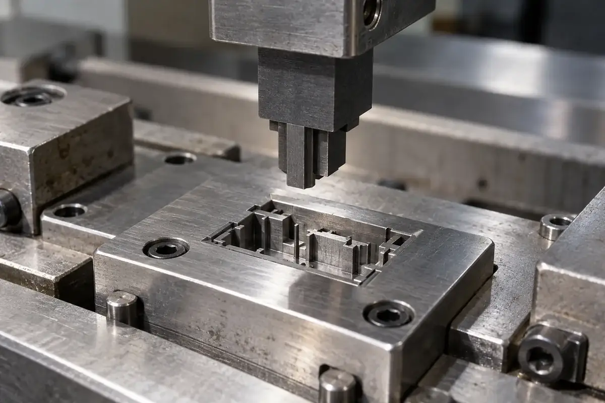
Consider a connector cavity with thin rib-forming details near a deeper retention pocket. One route may use wire EDM for separate through-feature segments and sinker EDM for the blind pocket. That combination can be more sensible than forcing every feature into one method. The decision belongs to the component design and its interfaces, rather than to a preference for one machine.
Include the operations before and after EDM
Milling, grinding and EDM are complementary operations. Larger accessible regions may be rough-machined economically before the fine details are produced. Ground faces can establish the locating relationship required for later operations. The order should preserve reliable references through changes in material condition and finishing, so the final profile is in the correct position as well as the correct shape.
The steel’s supplied and final condition affects that sequence. A tooling plan should say which dimensions are established before heat treatment and which are finished afterward, where applicable. It should also identify the surfaces used for setup. Otherwise, a precise local machining operation can still leave the feature incorrectly positioned relative to the mold pocket.
Surface condition is another separate requirement. A visually bright surface is not a complete specification for a molding face. Any remaining texture, edge treatment or finishing allowance must be appropriate for the plastic feature and the contact with adjacent steel. Polishing indiscriminately can change small edges and dimensions, so finishing needs defined limits.
Electrode manufacture and replacement can also influence a sinker route. A complicated electrode may be a precision component in its own right. Its geometry, wear allowance and intended sequence belong in the manufacturing review. A quoted machining route that omits the electrode work can give a misleading comparison with a wire-cut segment.
Judge the finished insert in its assembly
The replaceable-insert design guide explains how a component boundary can improve manufacturing access. A split may turn an inaccessible blind detail into a manageable through-feature. It also introduces a mating interface, so that benefit has to be balanced against registration, support and the potential molding witness at the joint.
Likewise, tool steel selection should be discussed with the intended route and final condition in mind. A steel name alone does not define the achievable surface, edge durability or repair procedure. The same nominal component can require a different practical sequence when the material condition or local geometry changes.
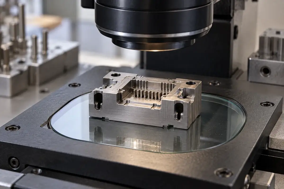
Inspection should connect the finished feature to the references that locate it in the mold. Checking a slot width without its position leaves an important question unanswered. For a comb-like insert, the review may need to consider the individual blades, their pattern and the supporting base together. The measuring method must be suitable for the actual access and feature size.
When reviewing precision connector mold inserts, ask the tooling proposal to connect each demanding feature with its access, machining sequence and final inspection condition. That explanation is more useful than a blanket statement that EDM is highly precise. It shows how the chosen methods will create a usable component within the complete tool.