
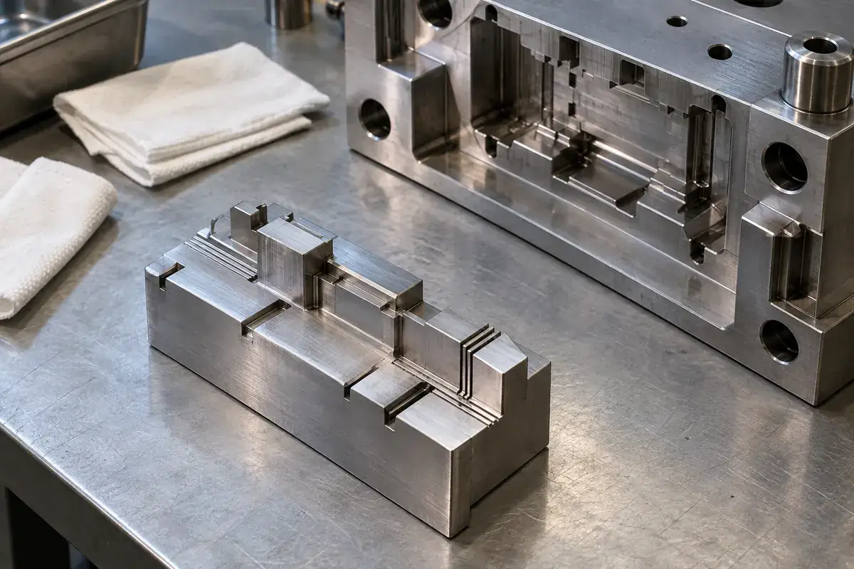
When a connector cavity begins to fill differently after a long run, a dirty vent is one possible explanation. It is not the only explanation, and it is not a reason to deepen the nearest groove immediately. Maintenance should first determine whether the intended air path is obstructed, damaged or unchanged. Those conditions lead to different actions and require different evidence before production resumes.
A removable steel insert makes that investigation easier only if the relevant surfaces are accessible and identifiable. The small vent land at the cavity boundary may be visible, while the relief channel behind it remains hidden against the mold plate. Cleaning the visible face without checking the route beyond it can leave the restriction in place and make a useful maintenance intervention appear ineffective.
Product design illustrations accompany the tooling and manufacturing explanations below.
Follow the air path beyond the cavity edge
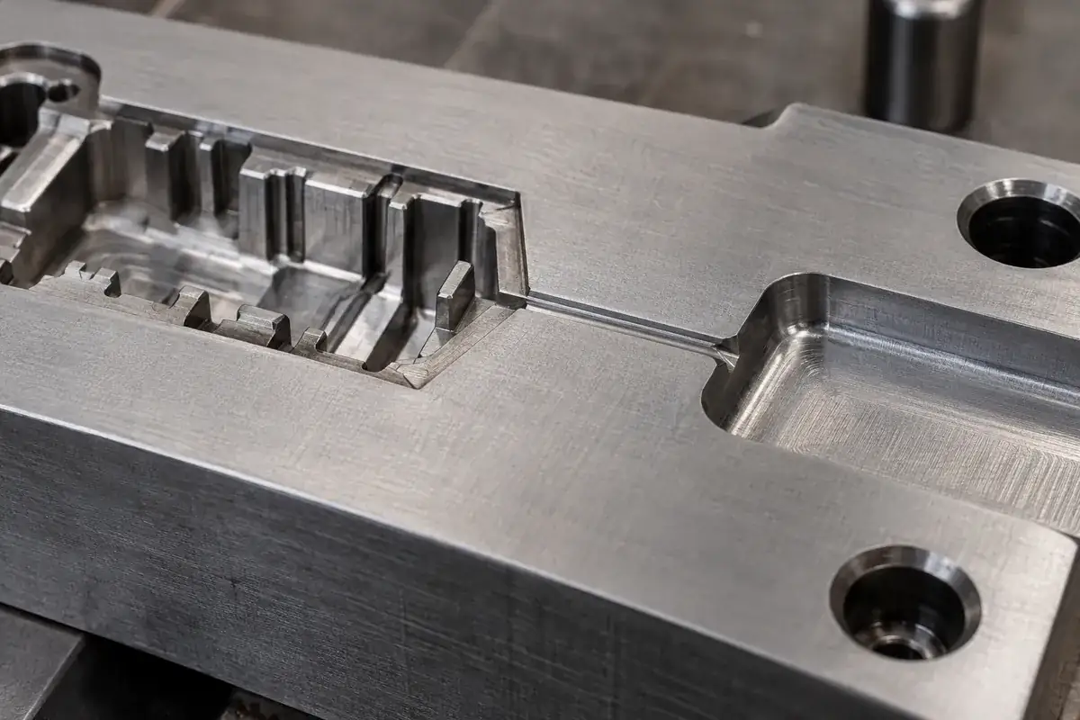
A conventional vent arrangement can include a controlled shallow land followed by a larger relief path. These regions have different functions. The land must pass air while limiting resin entry under the intended conditions; the relief path carries that air onward. The tool drawing should define the actual construction. A clean-looking cavity edge does not establish that the downstream route remains open.
On a compact connector insert, the route may cross an insert boundary or continue through another component. Its condition therefore depends on assembly as well as cleanliness. A misplaced component, damaged seating surface or unintended residue at an interface can alter the path. During disassembly, preserve enough location information to understand which surfaces worked together rather than examining each steel piece as an isolated object.
DME's venting guidance distinguishes vented ejector pins and porous plug vents, including their different cleaning needs. That distinction is useful even when a connector mold uses a custom machined vent: identify the construction before selecting the maintenance method. Instructions for a porous element should not be applied automatically to a ground vent land or a moving pin interface.
Remove deposits without silently reworking the insert
The first inspection should separate removable contamination from damaged steel. Deposits may obscure an edge, while wear or an indentation may have changed the feature itself. Cleaning can reveal which condition exists, but it does not restore lost material. Record the initial condition before aggressive work removes the evidence, especially when several cavities have developed different symptoms during the same production run.
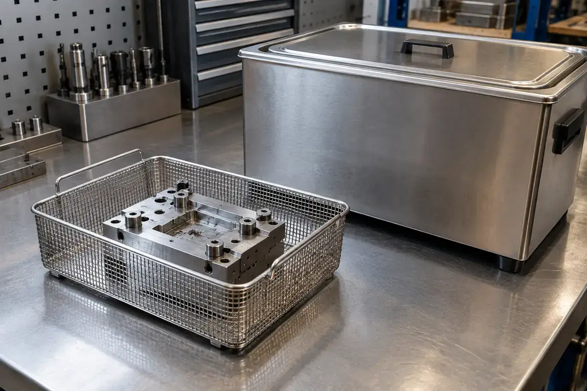
Choose cleaning chemistry and method for the resin residue, tool steel, coatings and adjacent components. DME's sintered vent FAQ directs users toward resin-specific cleaning recommendations and describes ultrasonic cleaning for that component type. It is a supplier-specific example of why the residue matters, not a universal instruction to immerse every precision connector insert in the same bath.
Loose abrasives, hard scraping tools or uncontrolled polishing can turn deposit removal into metal removal. The difference may be difficult to see on a narrow vent land. If a method is capable of changing the steel surface, its use needs a defined purpose and subsequent inspection. A vent that appears cleaner but has become wider or deeper is a modified tool feature, not simply a cleaned one.
Cleaning equipment also introduces handling questions. Support a small insert so fine projections cannot strike the basket or another component. Keep removed items separated, and follow the applicable equipment and chemical instructions for the selected process. A convenient batch of mixed tool parts may save handling time while making it harder to preserve delicate working edges and keep each insert associated with its original position.
Use the production pattern to guide the investigation
One cavity changing while neighboring cavities remain stable is a different pattern from a whole tool changing after a material or process adjustment. Record where the symptom occurs and when it appeared. That does not diagnose the cause by itself, but it narrows the comparison. Maintenance becomes more informative when the team can relate the cleaned insert to its prior cavity behavior.
Burning, incomplete filling and flash are observations, not unique signatures of a single vent defect. DME's molding troubleshooting guidance lists vent condition among several possible contributors. Use such guidance to frame an investigation rather than changing multiple settings at once. Otherwise, a temporary improvement may be attributed to cleaning even though another process change produced it.
The distinction from new vent design is important. Our discussion of thin-wall connector filling and venting concerns how flow and air evacuation are planned. This maintenance task asks whether the approved tool still presents that intended path. If the original arrangement proves inadequate, a design review can follow, but its revision should not be hidden inside a routine service record.
A useful maintenance interval grows from the actual process history and the component supplier's requirements. Resin formulation, deposits, cycle conditions and tool construction can differ between programs. Avoid borrowing a fixed cleaning frequency from an unrelated mold and presenting it as validated for every connector insert. Start with an agreed plan, record findings and adjust the interval through controlled review of the observed condition.
Verify the condition that returns to the press
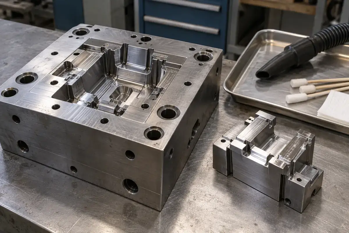
Before reassembly, inspect the working land and accessible relief surfaces for remaining deposits, damage and cleaning residue. Check the mounting faces too. A particle trapped under an insert can change its seating and create a new mismatch unrelated to the original vent problem. The article on steel insert datum inspection explains why those mounting references belong in the evaluation.
Where cleaning exposed damage or repair altered geometry, identify the changed feature and the inspection required for release. A maintenance photograph is useful for condition history, but it cannot replace a dimensional check where the acceptance depends on geometry. If the insert needs remachining, the responsible tooling team should approve that work against the applicable revision and mating components.
Restart verification should compare an identified post-maintenance condition with the agreed process and sample requirements. Inspect the affected cavities and any interfaces disturbed by the work. A first visually acceptable shot is encouraging, yet it does not automatically establish that the issue is resolved over the intended run. Define the confirmation appropriate to the change rather than assuming that cleaning alone closes the investigation.
For precision connector mold inserts, include service access and the intended vent route in the tooling discussion. A removable insert is most useful when it can be cleaned, inspected and returned to a known position without undocumented adjustments. Our mold tooling review connects those practical maintenance needs with the steel component definition and replacement strategy.