
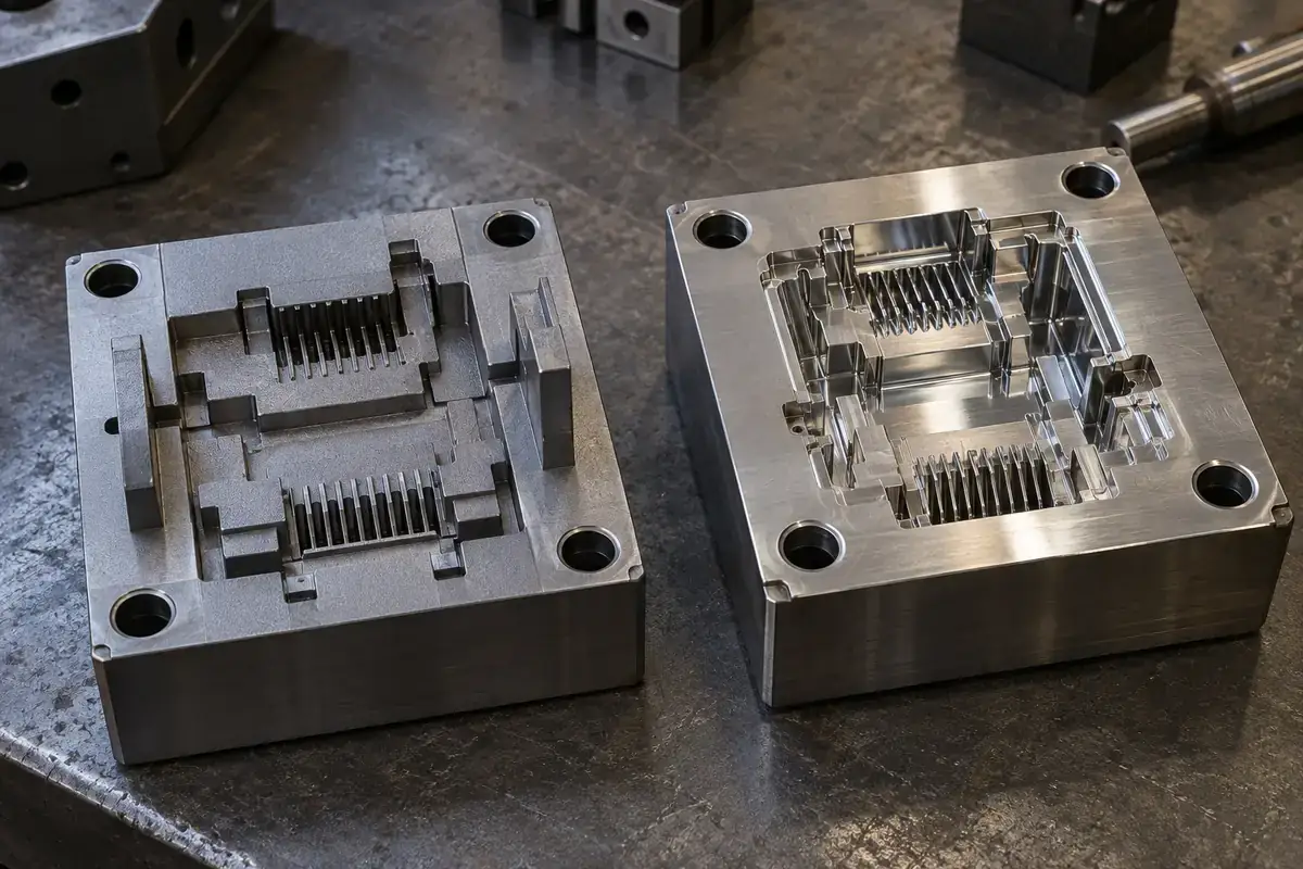
A mirror finish is easy to recognize in a photograph. A sealing edge that still has the correct geometry is harder to judge. On a precision connector mold insert, the second question can matter more. Fine ribs, terminal shutoffs and small cavity transitions leave little room for uncontrolled material removal, so requesting a shinier surface without defining its function can create a problem rather than solve one.
The useful discussion is therefore not simply how highly the steel can be polished. It is which surfaces require finishing, what the finishing must achieve, and which edges or dimensions must remain intact. A connector insert may need different treatments on its cavity walls, seating faces and nonworking relief areas. Giving every surface the same cosmetic instruction ignores those different jobs.
Product design illustrations accompany the tooling and manufacturing explanations below.
Read the surface through the component's function
A cavity wall helps define the molded surface and influences release. A shutoff land has a sealing role against another tool surface or a specified terminal region. A seating face locates the insert in its pocket. These surfaces may be adjacent on a very small component, yet a finishing method acceptable for one may be inappropriate for the next. Identify the boundaries on the tooling definition.
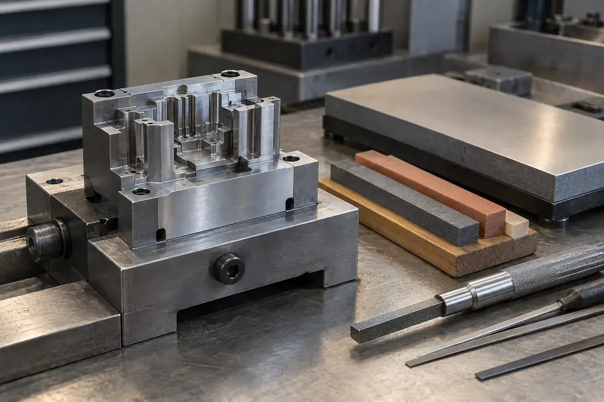
For example, a polishing lap moving across a narrow cavity wall can overrun onto a neighboring edge. The result might look smoother while the edge has become less distinct. This is a hypothetical manufacturing risk, not evidence that every polished insert will suffer it. It explains why access, tool stiffness, finishing direction and protected regions deserve attention before a detailed connector insert enters the finishing stage.
Uddeholm's guide to polishing mould steel distinguishes functional finishing from high-gloss polishing and connects the result with surface preparation. For a connector tool, use that distinction to define the required outcome. Reflectivity alone does not describe local shape, edge integrity or the condition of an inaccessible groove.
Account for the surface left by EDM
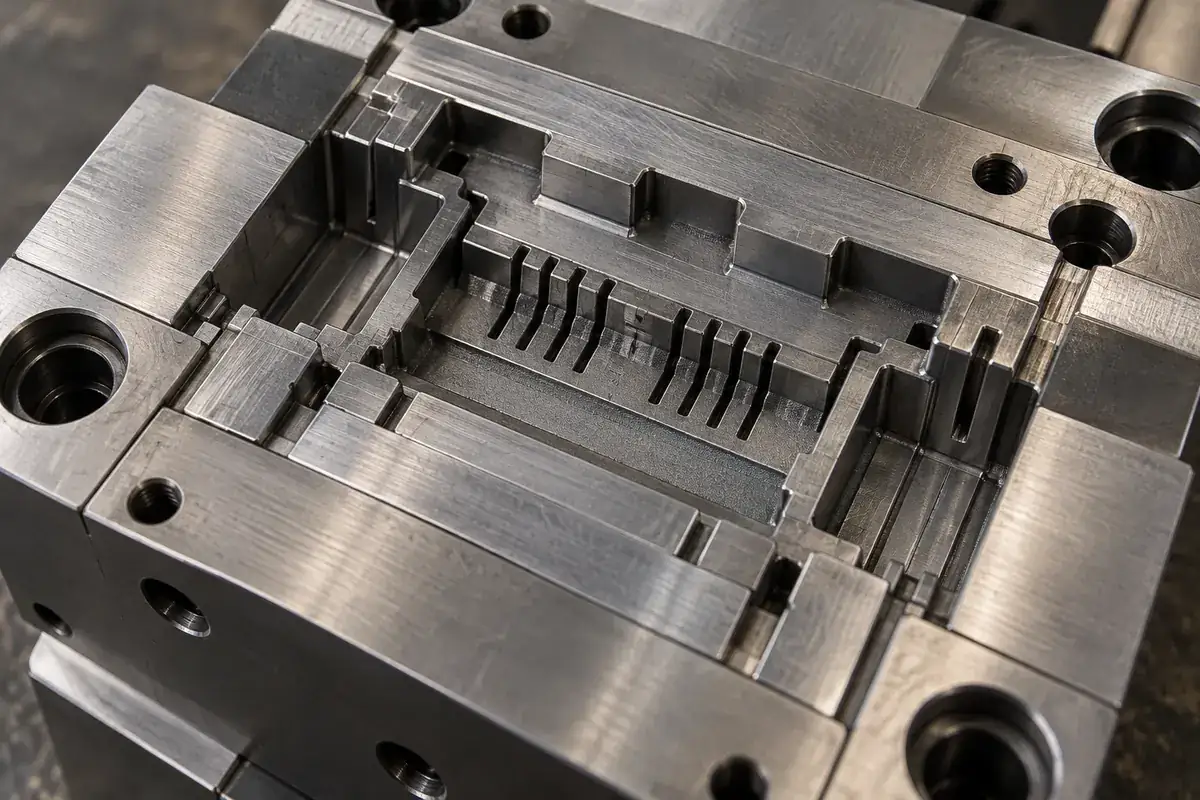
EDM is valuable where a cutter cannot conveniently create a feature, but the machining route also affects subsequent finishing. Uddeholm describes the thermally affected surface and potential cracking concerns in its EDM guidance for tool steel. The appropriate finishing and treatment sequence depends on the steel, the machining conditions and the intended working surface; it is not one universal removal allowance.
That distinction matters when the steel has narrow projections. Removing enough material to address a surface condition while maintaining the feature's final dimensions requires planning. It may be sensible to leave a controlled allowance before the finishing operation, but the allowance must come from the manufacturing plan. Adding an arbitrary polishing margin to a finished drawing can shift responsibility without actually defining a manufacturable process.
An EDM texture may be an intentional final surface in one region and an intermediate condition in another. A note that merely says remove all machining marks cannot express that difference. It may also encourage unnecessary work on a face whose texture was selected for a functional reason. Agree which surfaces are to remain as specified after EDM and which proceed to a separate finishing operation.
Access should influence the tooling arrangement before steel is cut. A deep narrow feature may be easier to finish and inspect when the insert is divided appropriately, but additional pieces introduce their own joints and assembly requirements. The decision is a balance between access and interface control, not an automatic argument for either a one-piece insert or the largest possible number of removable elements.
A surface number does not replace a geometric requirement
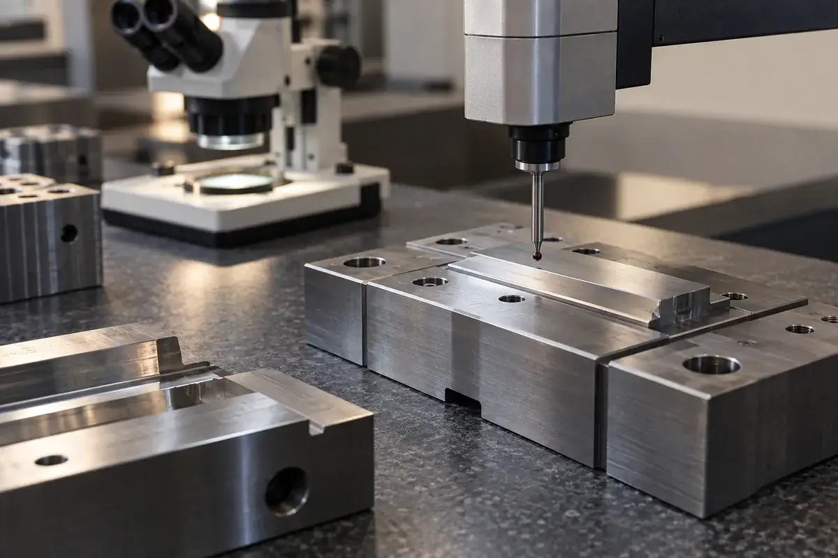
A roughness value describes a measured surface characteristic under a defined method. It does not, by itself, establish that a corner remains sharp enough, a wall remains straight or a shutoff land retains its intended width. Those are separate acceptance questions. A smooth, rounded edge can be quite different from a smooth edge that preserves the specified form, even when a nearby roughness trace looks satisfactory.
Small inserts also limit where a stylus can travel and which direction can be measured. A convenient flat land elsewhere on the part is not automatically representative of a deep cavity wall. If direct measurement is difficult, agree the alternative method and its limitations. Do not report a nearby accessible reading as though it were taken from the critical surface without making that distinction clear.
Visual assessment remains useful for local scratches, drag marks and finishing consistency, provided the viewing conditions are controlled. Lighting direction can make a polished wall appear very different without any physical change. Comparison samples or photographs need enough identification to remain meaningful after a revision. They support the agreed specification; they should not quietly become an undocumented replacement for it.
The steel and the molded plastic also need separate assessments. A tool finish does not guarantee identical appearance across different resin grades or processing conditions. Protolabs illustrates this distinction in its guidance on molded-part cosmetic appearance. Approve the specified steel condition, then evaluate the resulting component using its own appearance and dimensional requirements.
Check what changed during the final operation
Inspection before finishing establishes a useful baseline, but it cannot accept an operation that has not happened yet. Recheck the features most likely to change during polishing, deburring or coating. The insert datum and fit inspection discussion explains how to keep those measurements tied to the mounting references rather than comparing unrelated readings from convenient setups.
Deburring deserves an explicit boundary too. Removing a loose burr is different from adding a general edge break across every fine feature. The latter may be suitable for handling edges and unsuitable for a working shutoff. A drawing that identifies protected edges gives the finisher a better instruction than a broad demand for a completely sharp part or a completely burr-free part without functional context.
Maintenance can repeat the same risk on a smaller scale. A quick polish intended to remove deposits may also remove steel, and repeated touch-ups can become a geometry change. Link the approved surface condition to the insert cleaning and vent maintenance plan. If repair changes a working feature, treat it as a controlled correction followed by appropriate inspection rather than routine cleaning.
For custom steel connector mold inserts, provide the working-surface requirements alongside the cavity and mounting geometry. Our mold polishing review can then distinguish functional finish, appearance and protected dimensions. The objective is a usable finished insert with traceable geometry, not the most reflective photograph of a piece of steel.