
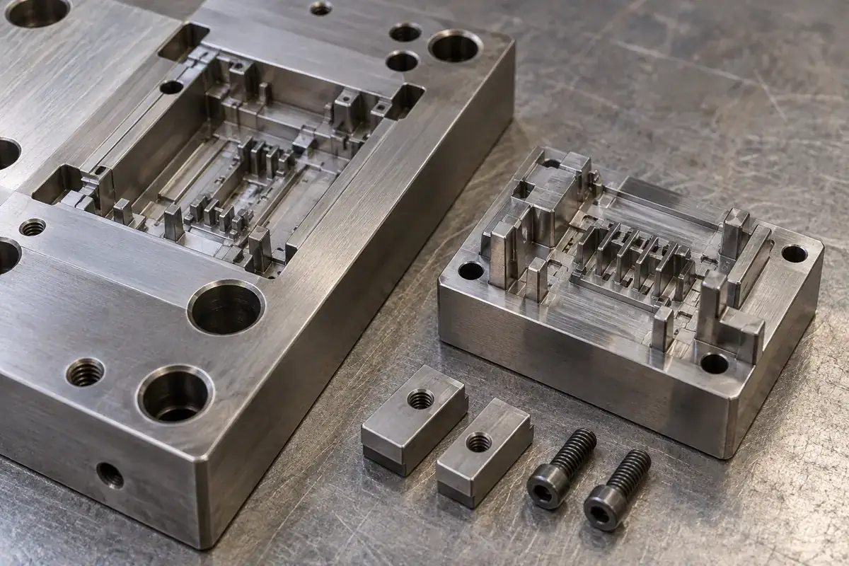
A damaged feature in a connector mold can be much smaller than the component that must be replaced to repair it. That is the practical attraction of a removable insert: isolate the region likely to need attention while retaining the rest of the tool. The benefit depends on where the tooling is divided and how the pieces register when assembled.
More pieces do not automatically make a better mold. Every additional interface must transfer load, preserve position and fit the thermal and maintenance arrangement. A useful design comparison therefore asks which problem a split solves, and which new relationships it creates. The answer may favor a separate insert in one region and a continuous block in another.
Product design illustrations accompany the tooling and manufacturing explanations below.
Choose the boundary around a useful task
A connector cavity may contain a repeated array of narrow features, a delicate latch-forming region and a larger surrounding wall. These regions need not share the same machining route or maintenance exposure. Dividing the tool can improve access to a difficult feature or allow a local replacement. Dividing it at an inconvenient position can instead put a joint across a sensitive plastic surface.
For example, a separate comb insert may provide access to narrow slots from a direction unavailable in a one-piece block. Its base can then locate within a larger holder. That changes the manufacturing problem, but it also creates a registration requirement between the comb and the adjacent cavity surfaces. Both effects belong in the decision.
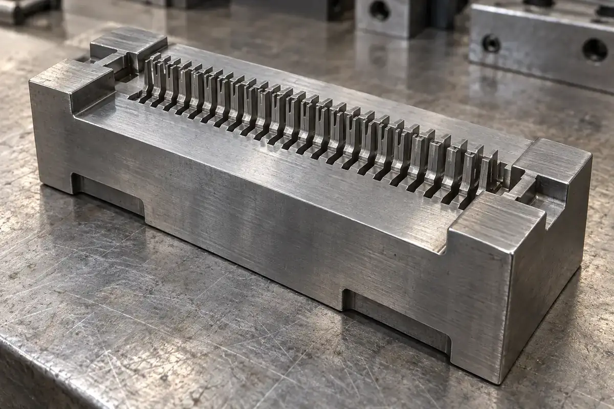
A monolithic component offers continuity between features machined from one piece. It may avoid a stack of locating interfaces and simplify some aspects of assembly. However, a local defect or design change may then affect a larger, more valuable component. The most economical initial construction is not always the most economical repair strategy over the intended program.
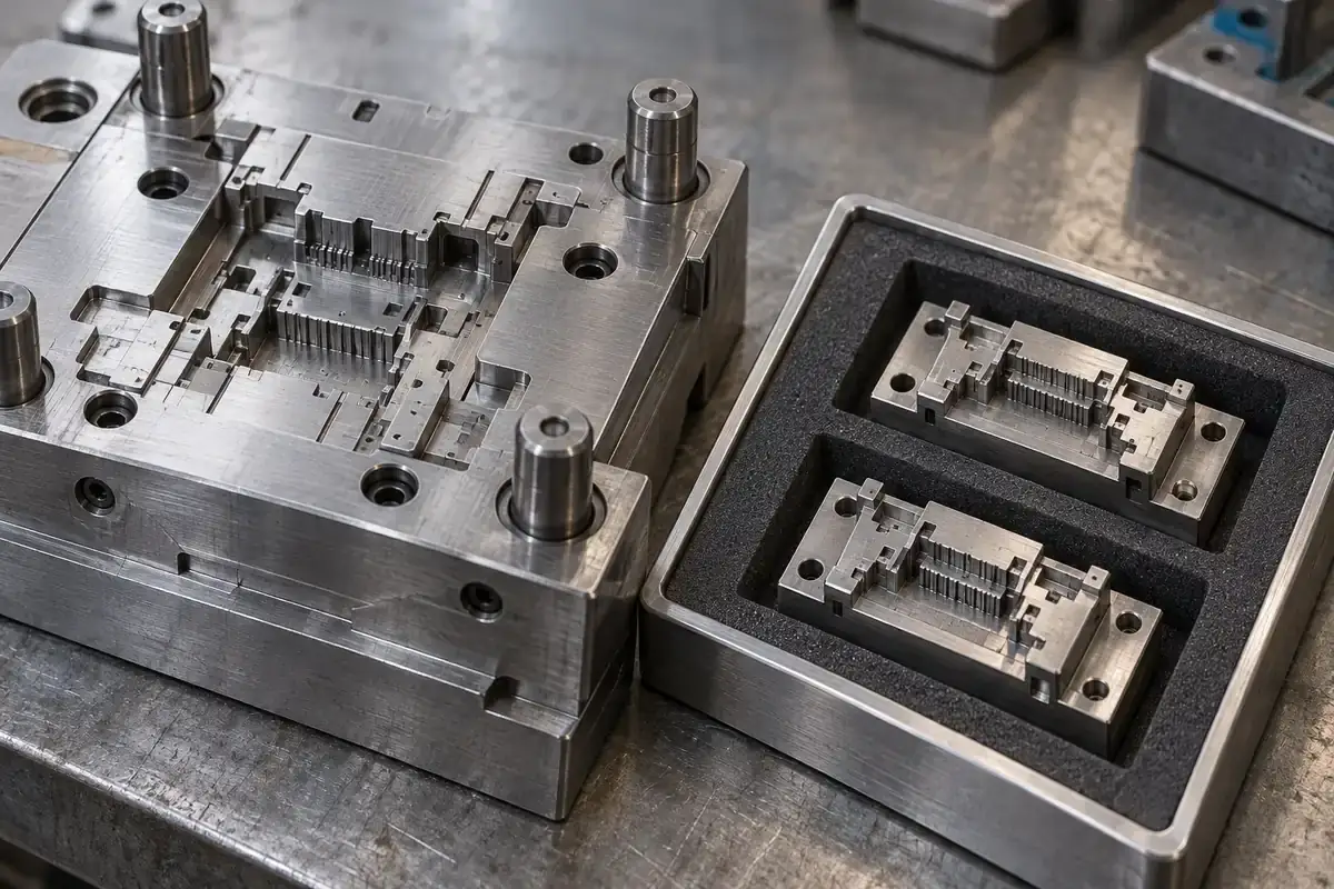
Standard tooling systems demonstrate the role of deliberate registration. Meusburger’s change-mold system uses dedicated positioning features for interchangeable inserts. That is an example of an engineered locating arrangement, not proof that an arbitrary connector insert will be interchangeable merely because it can be unscrewed from a plate.
Separate locating from retaining
The feature that holds an insert in place is not necessarily the feature that locates its working surface. Screws may provide retention while shoulders, seats or other defined surfaces establish position. If those functions are left implicit, a replacement can appear secure yet sit differently in the mold. The drawing should make the intended contact and clearance relationships understandable.
A component also needs support against the loads it will encounter. Thin working features may require a substantial backing region even when their plastic-forming geometry is tiny. Removing material to make an insert easier to extract can reduce that support. Review the assembled load path rather than judging the insert only as an isolated part on a CAD screen.
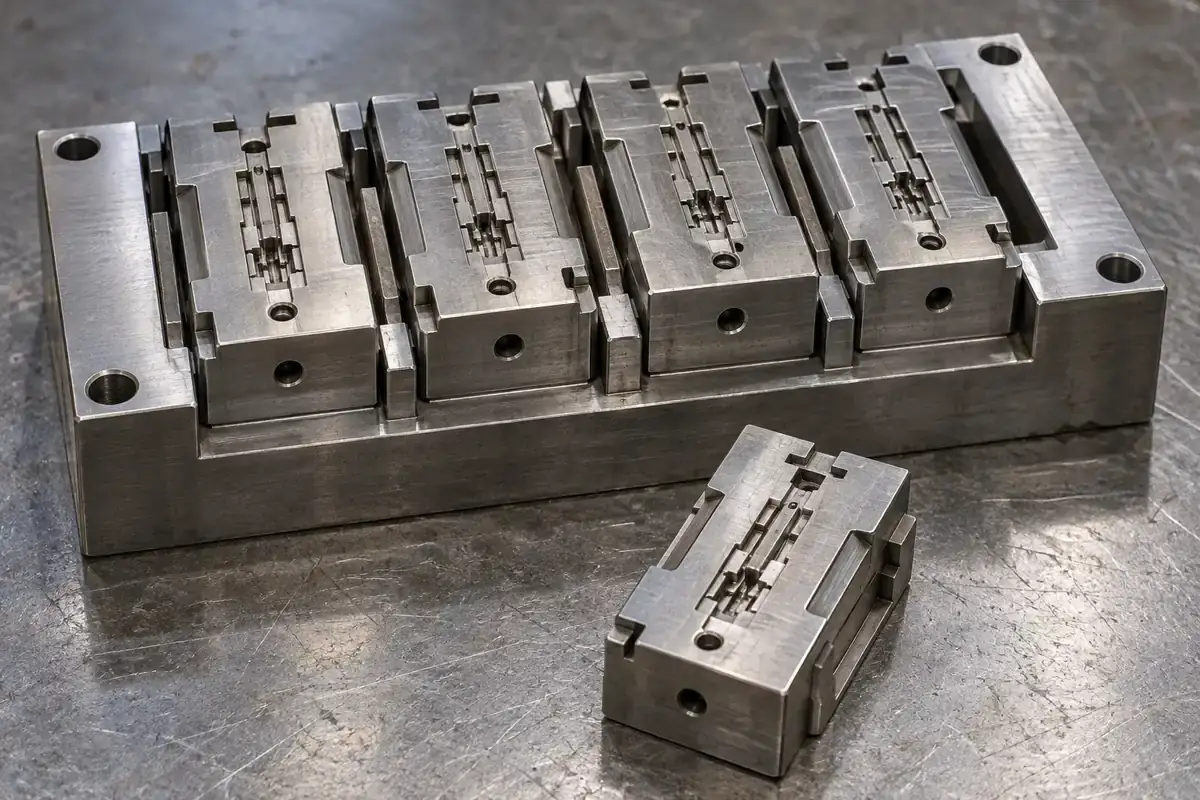
Assembly interfaces can influence the visible plastic boundary. A small mismatch between neighboring inserts may appear as a step or witness on a molded wall. Whether that matters depends on the feature’s function and specified acceptance criteria. Place divisions deliberately, considering contact openings, sealing regions, mating surfaces and other areas where a witness may affect use.
Thermal behavior deserves the same attention. A replaceable steel component contacts its holder through particular surfaces, and cooling access may be constrained by its size and location. Do not assume that the temperature behavior of a segmented construction matches a continuous block. The relevant question is whether the assembled arrangement controls the molding conditions required for the component.
Make replacement possible in the actual tool
A removable insert is useful only if it can be accessed without creating disproportionate disturbance elsewhere. Consider which plates, fasteners or neighboring components must be removed, and how delicate working surfaces are protected during extraction. A component that looks simple on a drawing can still be awkward to service when the complete mold is assembled.
The replacement sequence should also explain cleaning and seating. Debris on a reference surface can change the assembled position even when both components meet their individual dimensions. A maintainable tool offers access to inspect those surfaces and confirm the intended seating condition. This is a repeatability issue, not simply a matter of keeping the tool attractive.
Spare components need a defined relationship to the approved tool revision. A spare made before the final trial correction may no longer match the working insert. Keep the revised geometry, finishing requirements and any approved fitting allowance associated with the replacement. A stored piece of similar steel is not necessarily a ready-to-install spare.
Compare total consequences, not just component price
A segmented construction can add manufacturing and inspection work at the beginning. Each mating surface and retained component requires attention. Its value may appear later, when a local repair avoids remaking a larger block. That trade-off depends on the actual design, available spares and production needs; it does not justify a generic percentage saving or promised tool-life extension.
Consider an illustrative family of connector housings that differs only in one local keying feature. A changeable region might support that variation while preserving the common tool structure. But a different contact count could alter flow, ejection or surrounding geometry enough to require a broader review. Similar-looking product variants do not automatically belong in one interchangeable cavity arrangement.
The steel-safe adjustment guide helps determine whether an anticipated change can be made by removing steel, replacing a local component or revising a larger assembly. That direction matters when choosing a split. A well-placed insert can preserve options that a convenient but poorly located split would leave unavailable.
Manufacturing access is another reason to compare constructions. The article on wire EDM and sinker EDM for connector inserts explains how through-features and blind geometry lead to different routes. A proposed division should make the actual feature more controllable, rather than merely increasing the number of parts on the tooling bill of materials.
For precision connector mold inserts, a useful proposal identifies the feature being isolated, its locating and support surfaces, and the expected replacement or adjustment operation. This makes the trade-off reviewable before the tool is built. Replaceability then becomes a deliberate manufacturing capability with a defined interface, rather than a vague promise of easy maintenance.