
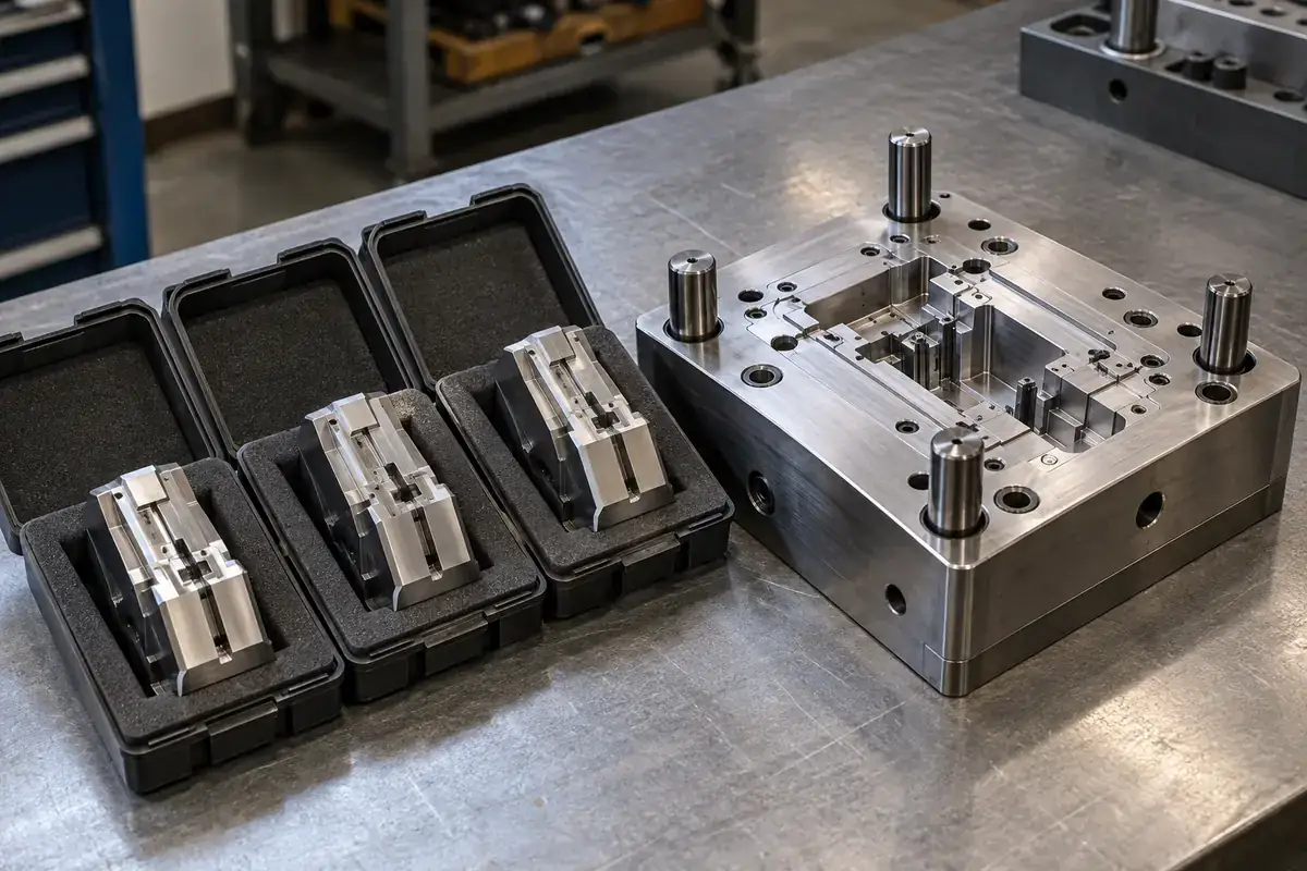
A spare insert on the shelf is reassuring until the tool stops and the replacement needs unexpected fitting. The spare may have been made carefully, and it may even match its drawing. The problem is that interchangeable can mean several different things: fitting one nominated pocket, fitting any approved position in a tool, or reproducing the intended molding behavior after installation. Those promises are not identical.
For a precision connector mold, the smallest visible cavity details often receive most of the attention. Yet replacement success also depends on the mounting envelope, seating height, locating features, neighboring inserts and service connections. A spare program becomes more useful when it defines these relationships explicitly rather than treating a duplicate cavity model as a complete manufacturing and acceptance specification.
Product design illustrations accompany the tooling and manufacturing explanations below.
Define the set of positions the spare must serve
A replacement dedicated to one cavity can be a sensible arrangement. It may account for that pocket's approved condition and the specific components that meet it. A spare intended to move across several positions has a broader requirement: the relevant interfaces must be compatible across that set. State which arrangement is being purchased so inspection and fitting decisions support the actual maintenance need.
Imagine a connector tool with several nominally identical cavities. During initial development, one pocket receives a controlled correction that is recorded only on a workshop sketch. A spare made from the earlier common model might then fit the other positions but not the corrected one. This hypothetical example shows why a position-specific revision can matter even when the molded connector geometry is supposed to remain the same.
Meusburger describes individual replacement and interchangeability within its own manufactured centring component systems. That is a useful example of interchangeability being designed into a controlled interface. It is not evidence that any custom cavity insert will be interchangeable merely because a standard locating component is used nearby. The whole relevant stack must be considered.
Capture what the installed insert actually depends on
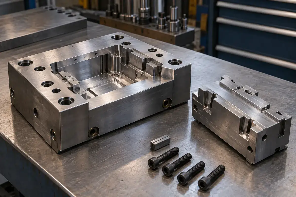
The working face may sit at a height established by a shoulder, backing plate or other assembly detail. A lateral position may come from a key or fitted side face. Another feature may only provide retention. Understanding this division prevents a common shortcut: tightening the fasteners and concluding that the insert is correctly located because it no longer moves. Retention and location are related but different functions.
Include the receiving components in the review. A worn or damaged pocket may no longer represent the condition used to approve the original insert. Copying that original insert cannot correct every change in the surrounding tool. Before revising a spare to fit, determine whether the discrepancy belongs to the replacement, the pocket or another part of the assembly that should itself be repaired.
Hand fitting does not automatically make an insert unacceptable. It does change what must be recorded if future replacements are expected to work the same way. Capture the approved correction, affected surfaces, mating position and resulting inspection. Without that information, the next spare is asked to reproduce knowledge that exists only in the first component and the memory of the person who adjusted it.
Dimensional reports should preserve functional references across suppliers and production batches. A cavity measured by best fit and a mounting block measured from its seat may each receive a satisfactory report without establishing their common relationship. The steel insert datum inspection article explains how an agreed reference system helps connect the replacement's working geometry to its installed position.
Treat coatings and final finishing as part of the fit
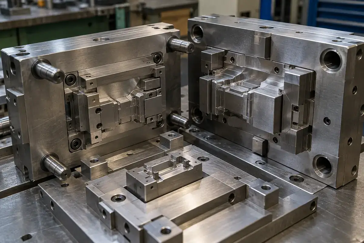
A nominally identical steel blank can become a different assembly proposition after final treatment. Coating location, finishing allowance and protected seating faces need to be included in the released definition. A drawing that is ambiguous about whether a dimension applies before or after treatment leaves the replacement supplier to make an assumption at precisely the point where interchangeability requires a shared answer.
The same issue arises with shutoff faces or polished working edges that meet a neighboring component. Surface preparation must preserve the approved geometry, and the mating condition may require evaluation as a pair. A high-gloss finish on one spare does not prove that its contact relationship matches the original. Keep the surface requirement and the interface requirement connected without allowing either to replace the other.
Temperature also deserves attention when defining a replacement check. A cold bench fit answers an assembly question in that condition; it does not reproduce every condition in an operating mold. The tooling team should identify which relationships require review at the intended operating state. That does not justify forcing a tight cold assembly or inventing a general expansion allowance without analyzing the actual materials and geometry.
A standard change-mold system provides another useful reference. Meusburger's change-mold documentation describes a defined insert-change sequence involving locating wedges and fastening arrangements. The lesson for custom connector tooling is procedural: replacement repeatability depends on both the component interfaces and the way the assembly is changed. Its published system performance should not be transferred to an unrelated custom tool.
Make a spare usable before the urgent changeover
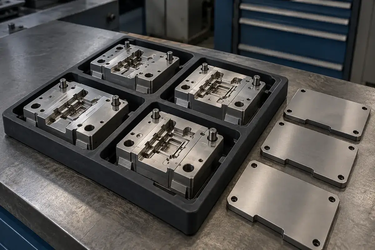
Where practical, evaluate the spare in its intended receiving arrangement before it becomes an emergency item. Confirm the agreed seating, alignment, clearances and assembly sequence, then document the result. A component accepted only as a loose steel part may still be a valuable spare, but its status should not imply that all fitting and trial work has already been completed.
Packaging and storage preserve that status. Fine steel features can be damaged by contact with another insert, and a seating face can become contaminated during repeated handling. Separate protection for working surfaces and clear internal identification help keep the approved item associated with its revision and nominated positions. The public product photograph does not need those identifiers, but the maintenance system does.
After installation, verify the outcome appropriate to the disturbed interfaces and production requirements. A spare that fits correctly may still require an identified molding check before routine production resumes. The article on insert acceptance and mold trials separates steel approval from sample approval so the replacement record states exactly which stage has been completed and which remains open.
Our precision connector mold insert review can define a position-specific replacement or an intended interchangeable set from the relevant tool information. For replacement manufacture, include the current assembly revision and any approved fitting history in the precision mold component review. That preparation turns a spare from a nominal duplicate into a component with a clear, reviewable role in the tool.