
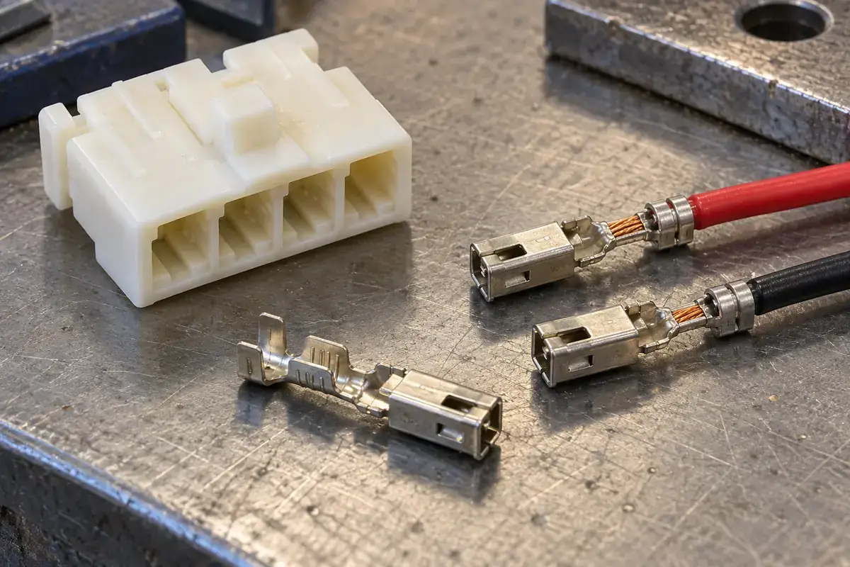
A terminal that stops halfway into a housing creates an immediate temptation: push harder or enlarge the plastic opening. Both actions can erase the evidence that explains the problem. The contact may be rotated, a crimp wing may be outside its intended envelope, or a normal retaining feature may be approaching the wrong side of the cavity.
The useful first question is where movement stopped and which two surfaces touched. Insertion is a sequence, not a single final dimension. The contact box, retention feature, conductor crimp and insulation support pass different locations at different times. Following that sequence turns a vague complaint about a tight housing into a specific interface that can be examined.
Product design illustrations accompany the assembly and manufacturing explanations below.
Keep the first failed assembly as evidence
Set aside the affected housing, terminal and wire together, with their orientation recorded. Do not mix them with parts that have been repeatedly inserted and removed. Repeated attempts can flatten a lance, scrape the cavity or bend the contact, making it difficult to distinguish the original interference from damage caused during troubleshooting.
Record the approximate stage of travel and whether resistance began immediately, increased gradually or appeared near the expected seated position. An obstruction at initial entry suggests a different relationship from a stop after the contact box has passed. This observation does not diagnose the cause by itself, but it narrows the portion of the assembly worth comparing.
Inspect under suitable magnification for witness marks on both components. A bright edge on a metal wing has more meaning when a corresponding mark appears on the housing. Absence of an obvious mark is not proof of clearance: a soft jacket may deform without leaving a clear trace. Compare the physical observations with the drawing-defined insertion path.
Check the finished contact, not only its part number
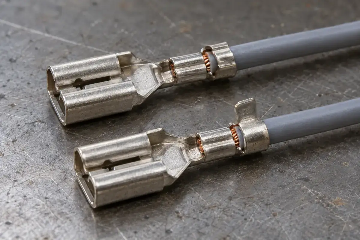
A matching part number does not establish that the contact still has its intended shape. The contact box can be squeezed by handling, the crimped section can bend relative to the mating axis, or a support wing can protrude. Review the affected feature against the applicable contact drawing and termination specification before assigning the problem to the plastic.
Wire choice belongs in that review. The same nominal conductor gauge can arrive with a different insulation diameter, changing the formed support-crimp envelope. The separate guide to wire gauge and insulation diameter explains why a substitution can create a housing-fit problem even when the electrical bill of materials appears unchanged.
Do not trim a metal wing or squeeze the contact with improvised tools to create clearance. That can affect the termination or contact behavior and removes the possibility of a representative comparison. Correct the wire, terminal or crimping setup through its approved process, then use newly prepared samples to determine whether the housing interface remains a concern.
The JST terminal and connector handling precautions emphasize avoiding deformation and abnormal loads during handling. The practical consequence for diagnosis is simple: a part damaged during an insertion attempt is no longer a clean sample of the incoming contact or the original molded cavity.
Distinguish orientation from clearance
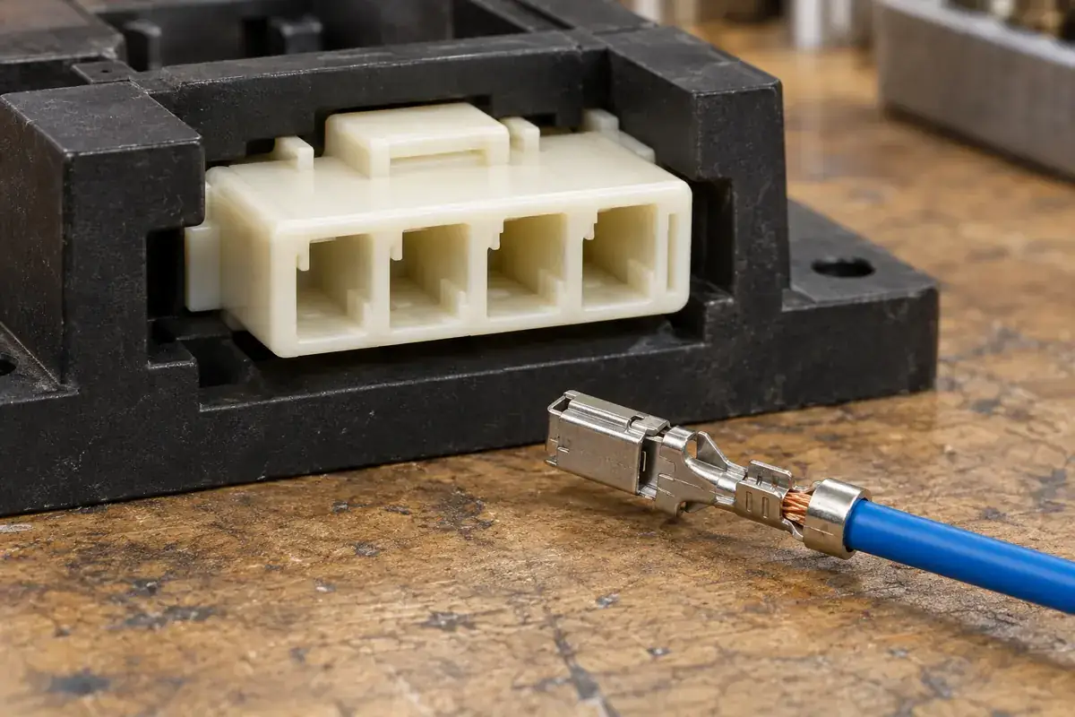
A contact can look rectangular and still be asymmetric. A lance, shoulder or folded guide feature may belong on one side of the cavity. If it approaches the wrong wall, enlarging the opening may merely allow incorrect insertion to continue farther. Confirm the approved orientation before comparing nominal width and height.
Use the retaining feature and cavity guide as references rather than the direction in which the wire naturally rests. A twisted crimped wire can bias the contact toward an incorrect rotational position. The article on terminal orientation and keying explains how geometry, assembly fixtures and visual references can support the intended loading direction.
Once orientation is established, identify the narrowest relevant cross sections. A cavity entrance may be generous while an internal shoulder or guide rib defines the true limit. Draft, local radii and the retaining mechanism should be evaluated in the actual travel direction. Reducing the entire problem to the rear opening dimension can miss the interfering feature.
Also check the entry path imposed by the fixture or neighboring wires. A contact presented at an angle occupies more transverse space than the same contact traveling along the intended axis. Correcting an approach problem may require better access or support rather than a larger cavity, especially when later wires in the assembly are harder to load than the first.
Use comparisons that isolate one variable
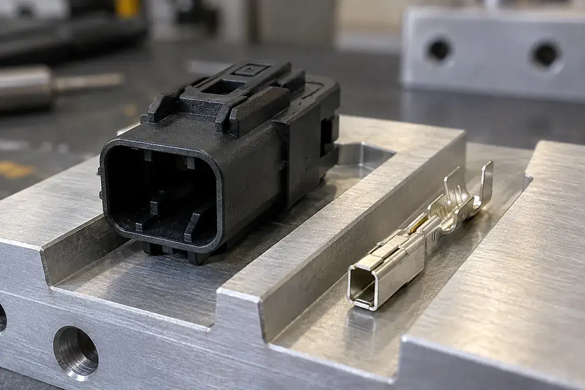
Compare approved reference contacts and affected contacts with identified reference and affected housings, using the same controlled assembly method. This is more informative than trying random combinations until one works. Keep samples traceable to the relevant wire lot, crimp setup and molded cavity so a pattern is not hidden inside an average result.
If only wire-terminated contacts show the interference, examine what termination added to the envelope. If both bare and terminated contacts stop at the same position, review orientation and the contact-box interface. These are investigation directions, not automatic verdicts; the final cause still needs dimensional and physical evidence from the specific parts.
A housing change should then target the identified relationship. Opening a nonfunctional approach region is different from reducing a retaining shoulder or removing a guide. Before approving steel work, review how the change affects contact support, retention and misassembly prevention. An easier insertion path is useful only when the seated component still performs its defined mechanical role.
For custom molded wire-to-board housings, supply the failed assembly evidence together with the current contact and wire definitions. Agree a controlled trial using corrected parts and a defined seating check. That sequence turns an insertion complaint into a reviewable manufacturing decision without relying on force, appearance or an unsupported assumption about which supplier caused it.