
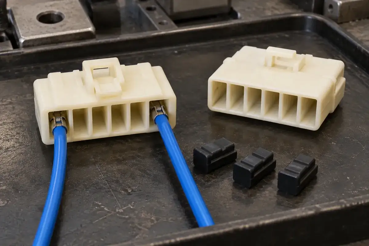
Using one connector housing across several harness versions can simplify purchasing and tooling. One version uses every circuit; another leaves two positions empty. The plastic looks identical, but the unused cavities create decisions about assembly errors, access and contamination that a circuit list alone does not answer.
The first question is what closing the cavity is meant to achieve. Preventing an operator from loading the wrong circuit is different from protecting a contact area during handling, and both are different from sealing a complete connector assembly. A plug should be selected against that purpose rather than added simply because an empty hole looks unfinished.
Product design illustrations accompany the assembly and manufacturing explanations below.
Start with the population map, not the plug
Define the populated and unpopulated positions for each approved harness version. Use one stated viewing direction, because a front-face drawing and a wire-entry view can mirror the apparent layout. Connect the population map to the circuit identification and housing orientation features so the intended empty positions remain unambiguous at the assembly station.
Consider whether the mating half contains a contact at an unused position. An empty wire-side cavity does not necessarily mean that nothing enters it during mating. A blocking feature must not collide with a mating pin or redirect that pin into an adjacent wall. Review the full mating envelope before deciding where a plug may stop.
A platform may also need future optional circuits. A removable blocker preserves a different service route from a permanently closed molded cavity. The latter can simplify kitting but creates a separate housing definition. Choose between them using expected configuration changes, mistake prevention and the cost of managing additional part variants.
Keep blocking and sealing as separate requirements
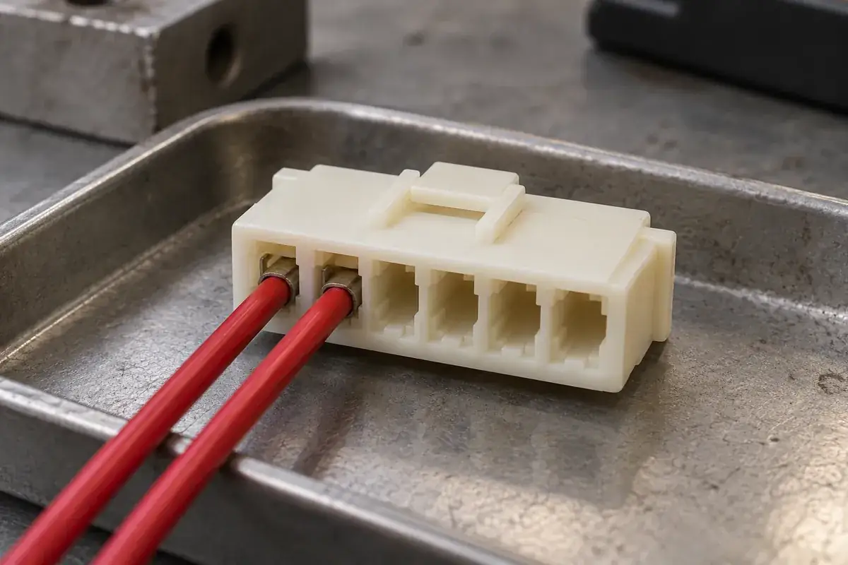
In an unsealed wire-to-board connector, a simple plastic cavity blocker may prevent terminal loading or reduce the chance of loose material entering a particular opening. It does not make the mating interface, latch openings and wire entries watertight. Closing one opening cannot establish an environmental protection rating for the entire assembly.
Sealed connector systems use specific interfaces and components to address those other paths. A cavity plug may work with an elastomeric seal or another defined sealing arrangement. Its shape, surface condition and installed position belong to that system. Copying the visible diameter of a catalog plug is not enough to reproduce its function.
TE's NTSEAL cavity-plug information describes plugs for unused positions in that named connector family. It supports treating the plug as a matched system component. Those product-specific claims do not establish sealing performance for a custom unsealed housing or a different plug geometry.
Check retention without obstructing the useful interfaces
A blocker must remain in its intended position through the agreed handling and assembly sequence. Its retention feature may act on a housing shoulder, a rear cover or another designed interface. If it borrows the contact retention feature, confirm that it uses that feature as intended and does not permanently deform the cavity needed for a future terminal.
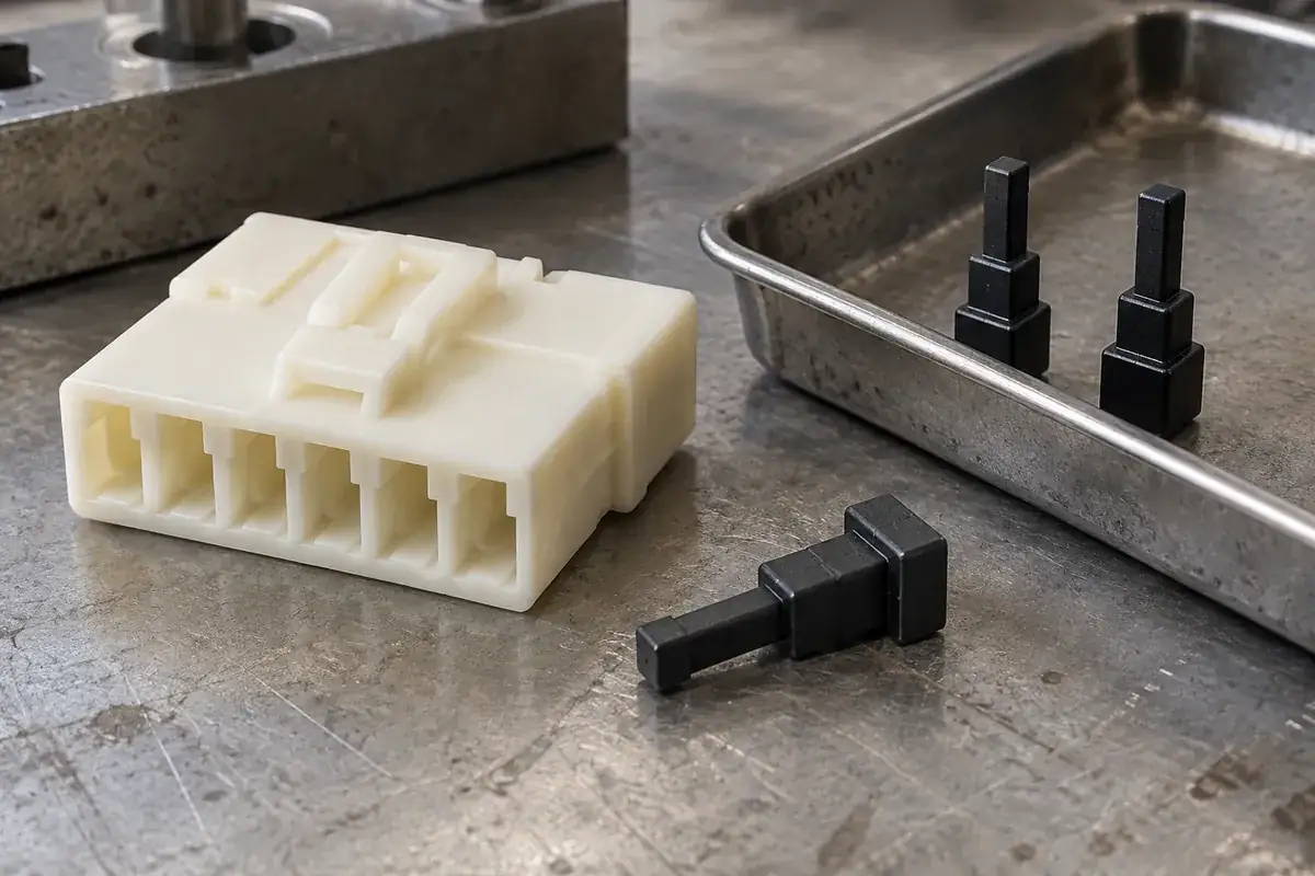
The installed depth matters at both ends. A blocker that protrudes from the rear can interfere with a cover or crowd adjacent wires. One that projects toward the mating face may obstruct a pin or prevent the connector halves from reaching their stops. Review the entire insertion path and final envelope rather than judging the plug from a rear-view photograph.
Removal also needs a defined direction. A serviceable blocker should have a suitable grip or tool interface that remains accessible after neighboring cavities are wired. Otherwise, a seemingly reversible configuration can require damaging the blocker or probing the contact cavity to change it. That may be acceptable for a replace-on-removal item, but it must be planned.
Plan the assembly sequence around adjacent wires
Installing blockers first may make empty positions obvious and prevent accidental terminal insertion. It can also obstruct access to neighboring terminals or the inspection view. Installing them later preserves access but leaves the assembler responsible for recognizing the correct open cavities throughout wire loading. Compare both sequences with a representative partially populated harness.
A secondary lock or rear cover can add a further constraint. Determine whether it must pass over the blocker, retain it or avoid it entirely. Do not assume an empty-position configuration behaves like a fully populated one. A feature that detects terminal position may react differently to a blocker that has no matching terminal geometry.
Use configuration-specific kitting where practical. Plug color may help distinguish variants, but shape and controlled identification are more reliable than color alone when lighting, supplier lots or adjacent components change. Verify the part identity and position through the approved assembly method instead of relying only on visual similarity.
Inspect the selected configuration, including the empty positions
An electrical test may confirm the circuits that are present while saying little about whether an unused cavity has the correct blocker. Include missing, misplaced and incompletely installed blockers in the assembly inspection. If a blocker has an observable final position, agree how it will be assessed without pushing it further during the check.
For a sealed assembly, environmental validation must represent the intended population pattern and its matching seals, plugs and mating half. For an unsealed assembly, inspection can focus on the stated mechanical and handling purposes. Keeping these scopes explicit makes the drawing and acceptance record easier to use.
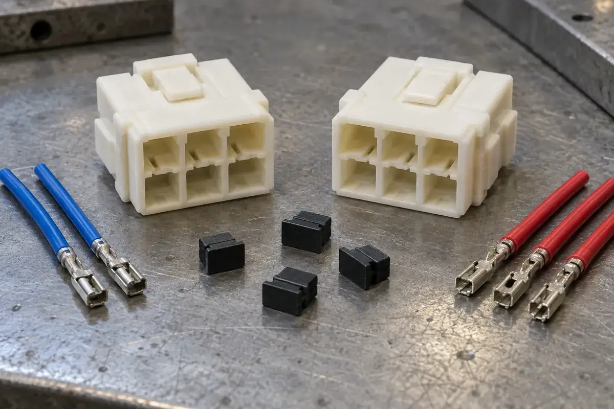
A useful review package contains the housing and mating definitions, population maps, blocker purpose and installed-depth requirements. Add the planned repair route if circuits may be changed later. These are concrete inputs for a custom wire-to-board housing and its optional components.
For the wire-loading portion of the process, the guide to sequential terminal loading explains how cavity access changes as the harness fills. Considering that sequence early avoids a blocker that solves one mistake while creating another.