
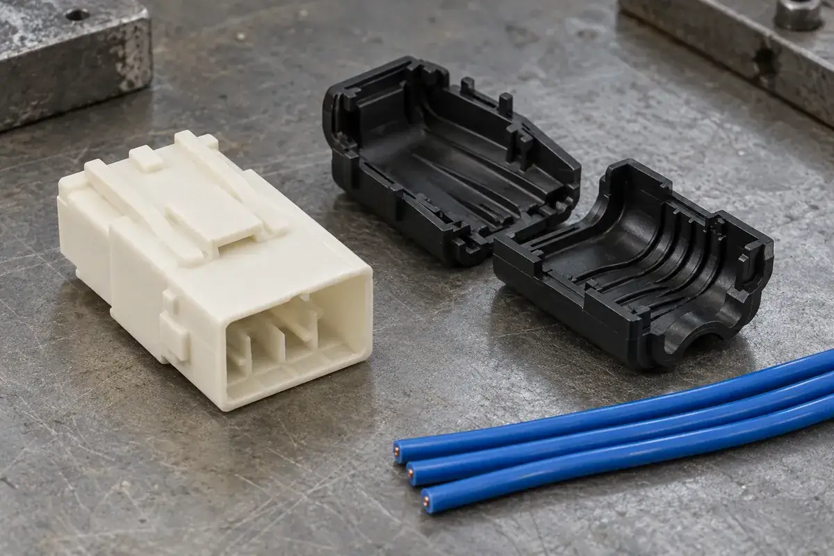
A rear cover can make a harness look orderly while hiding a crowded crimp area. The wires enter the cover easily when it is open, but the closing half pushes them sideways, traps one lead at the seam or transfers pressure directly into the terminals. The outside shape may fit the product perfectly and still create an assembly problem inside.
The cover needs a defined job. It may guide the wire exit, protect the rear entries, provide a place for an agreed cable restraint or combine these functions. Giving each function a specific interface makes it easier to decide where clearance is needed and where controlled contact with the wire bundle is intentional.
Product design illustrations accompany the assembly and manufacturing explanations below.
Preserve the space used by the crimp and terminal
Begin with the terminated wires fully seated in the housing. Include the conductor crimp, insulation support and transition into the flexible wire in the assembly model. A simple cylinder representing only the wire insulation can omit the widest or stiffest part of the termination, particularly where several crimp envelopes sit close together.
The terminal must remain in its intended position when the cover closes. If a cover feature touches the crimp, determine whether that contact is deliberate and whether the terminal design permits the resulting load. A cover should not be used to push an incompletely inserted terminal into place unless that function has been specifically designed and validated.
Different approved wires can change the available space even when their conductor size is similar. Insulation diameter and stiffness affect both bundle volume and how the wire bends behind the terminal. The wire-gauge and insulation-diameter review explains why the electrical wire designation alone is insufficient for this mechanical check.
Follow the moving edge as the cover closes
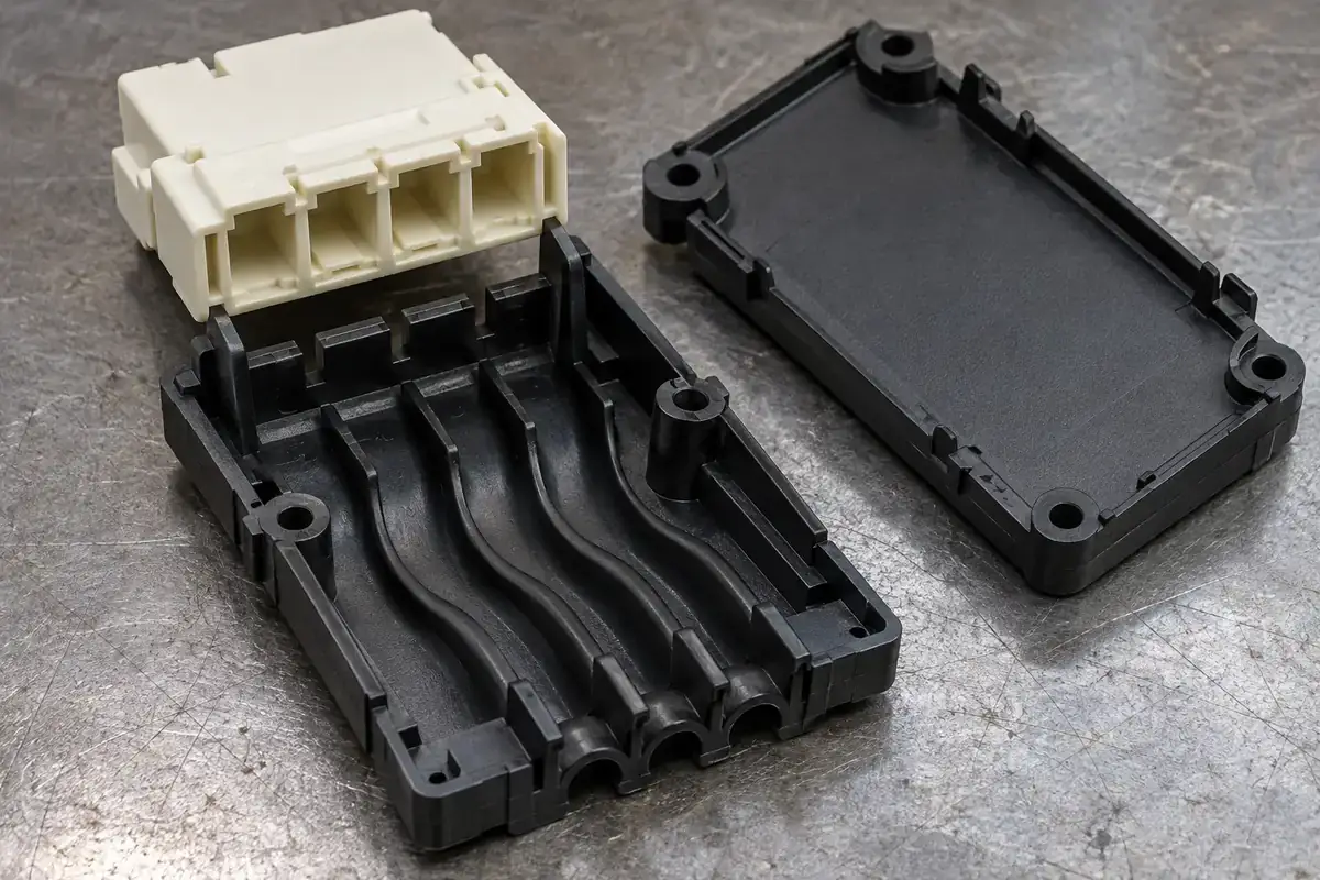
A final-state section can show generous clearance while the closure path sweeps through a wire. Hinged covers, sliding caps and two-piece snap assemblies each have a different moving envelope. Review intermediate positions with the wires in their realistic, imperfectly arranged state rather than assuming every lead remains centered.
Parting edges and latch entrances are common places for a lead to become trapped. A local guide can move the wire away from the seam, but it also occupies bundle space and can concentrate pressure. Shape the guide around the expected wire route and check whether it remains helpful when the bundle is at the large end of its approved range.
A cover that requires squeezing the bundle by hand to achieve closure is giving useful feedback about the layout. Investigate the reason instead of treating that manipulation as an undocumented assembly skill. The intended arrangement should be explainable through the housing position, wire order and cover movement.
Separate wire guidance from strain relief
Routing the bundle in a chosen direction does not automatically relieve tension at the contacts. To act as strain relief, an agreed feature must transfer relevant loads into a suitable support without unacceptable damage or movement. A loose tunnel may guide wires while providing little resistance to a pull along their length.
If a tie, clamp or separate restraint is part of the design, include it in the definition. Its position, contact area and installation method affect the resulting load path. Tightening a restraint more aggressively is not a substitute for a geometry review, especially when individual wires rather than a jacketed cable carry the pressure.
TE's AMPSEAL accessory catalog describes backshell arrangements and a wire-tie recommendation for a specified configuration. The useful lesson is that the cover and restraint are evaluated together. Its guidance applies to that product family, not as a universal instruction for a custom cover.
Let the exit direction fit the installed harness
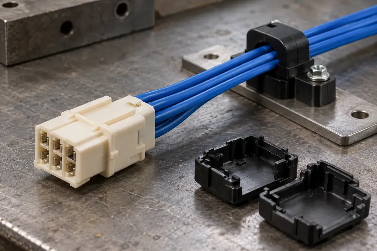
A right-angle exit can help packaging but may require a bend immediately behind the crimp. A straight exit provides a different route and may need more enclosure depth. Compare both with the intended wire construction and available support positions. There is no single bend allowance that can be inferred from the housing's outside width.
Where the bundle splits into branches, consider whether the division occurs inside or outside the cover. Internal branching can reduce external bulk while making wire placement more complex. An external split may be easier to assemble and inspect but need more free space. The choice should reflect the harness build and service method as well as the packaging target.
A cable route that bends around the connector release tab can obstruct servicing even if it fits statically. Check the latch movement and housing grip areas after the cover is installed. Keep this separate from individual-contact access: reaching the mating latch and reaching a terminal release window are different operations.
Design a cover that can be checked and reopened appropriately
Define how full closure is recognized. A cover seam, latch position or another visible feature may provide useful evidence, but only if a trapped wire cannot produce the same appearance. Inspect the assembly at the stage when the crimp area and wire placement can still be seen, then confirm the intended cover state after closing.
If service requires reopening, provide the approved release route and specify whether the cover may be reused. Some snap features are suitable for a controlled service operation; others are intended to be replaced. Avoid turning a single successful opening into a general reuse promise without the corresponding design and validation.
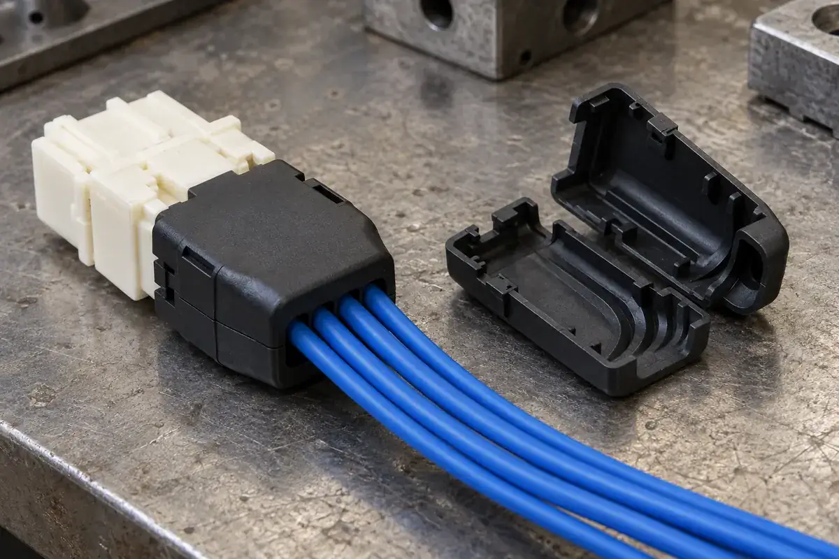
In the molding review, connect these functional requirements to the parting line, latch detail and allowed surface witnesses. The critical question is whether the manufactured cover preserves the agreed internal clearances and closure path. A clean cosmetic surface alone cannot answer that question.
For a custom wire-to-board housing and rear cover, share the terminal definition, wire range, harness route and restraint arrangement together. Review the cover open, moving and closed. Those three states reveal problems that a final assembly rendering can easily conceal.