
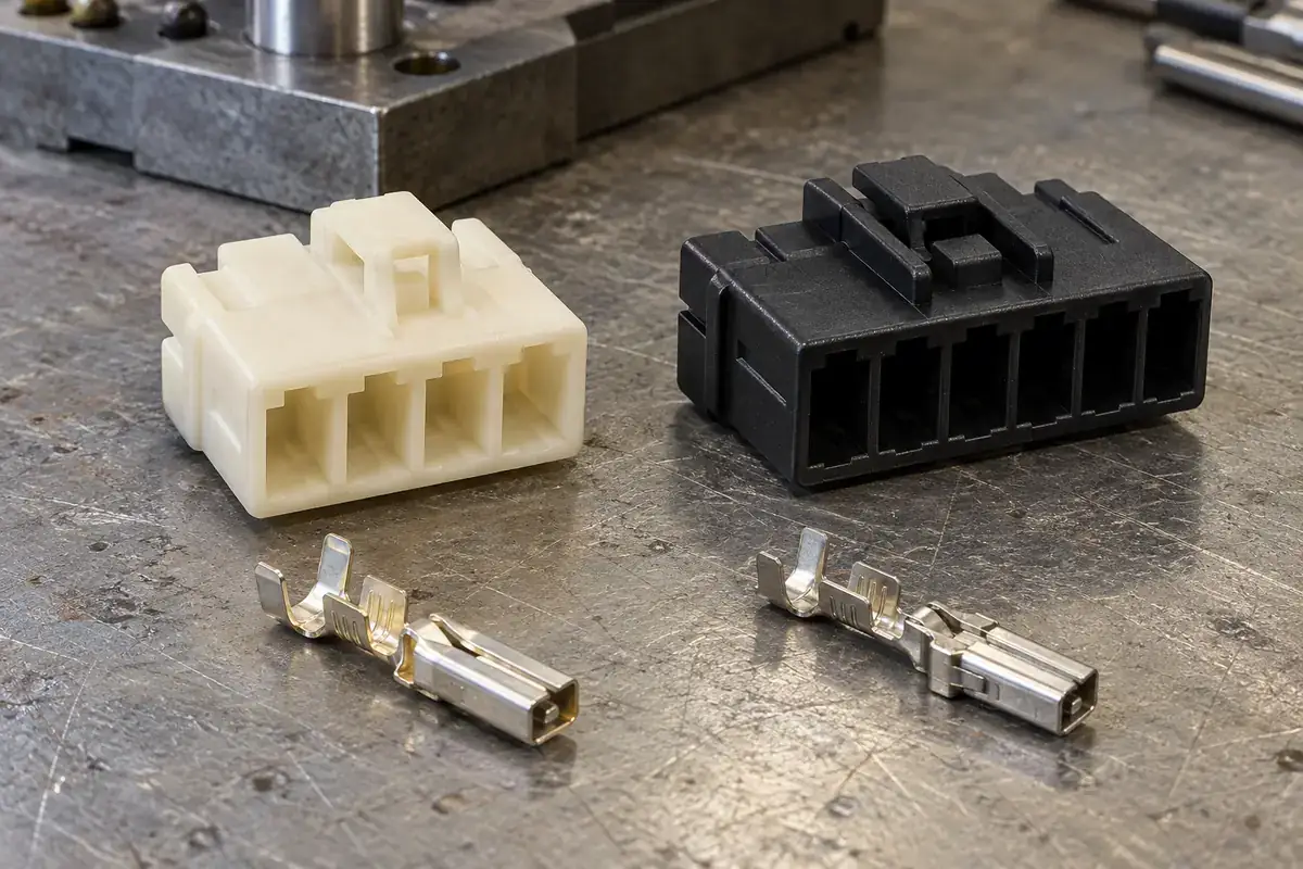
A connector can fit the available space and still be awkward to assemble. Its wire-side housing may accept the chosen terminal, yet leave no room to insert the last wire or release the latch after the enclosure closes. Choosing a wire-to-board connector type therefore starts with the sequence in which the wire, terminal, housing and board become an assembly.
For a custom molded component, that sequence also defines what the housing supplier needs to review. A drawing of the outer shell alone cannot explain which metal feature must pass through a cavity, where a contact should stop, or how the operator will reach it. The useful comparison is between complete mechanical arrangements, even when only the plastic part is being sourced.
Product design illustrations accompany the assembly and manufacturing explanations below.
Start with the wire termination, not the connector outline
In a crimp-and-insert arrangement, the wire is terminated before the contact enters the housing. The molded cavity must accommodate the finished crimped terminal along its insertion path and then retain it in the specified position. Both the contact box and the crimped rear section matter, although they perform different jobs and may occupy different portions of the cavity.
An insulation-displacement arrangement has a different assembly sequence. The wire is located relative to the contact system and pressed into the termination geometry, often with a cover or supporting housing feature involved in positioning. Replacing a crimp housing with an IDC-looking shell is not a simple change of entrance shape; wire placement, tooling access and assembly control change with it.
Soldered wire-to-board arrangements require their own review of heat exposure, wire support and access. A housing that is comfortable to load with loose crimp contacts may not suit a soldering operation near the plastic. Select the termination approach with the electrical and harness teams before deciding that a similar external profile means two housings are interchangeable.
Identify the two mating halves clearly
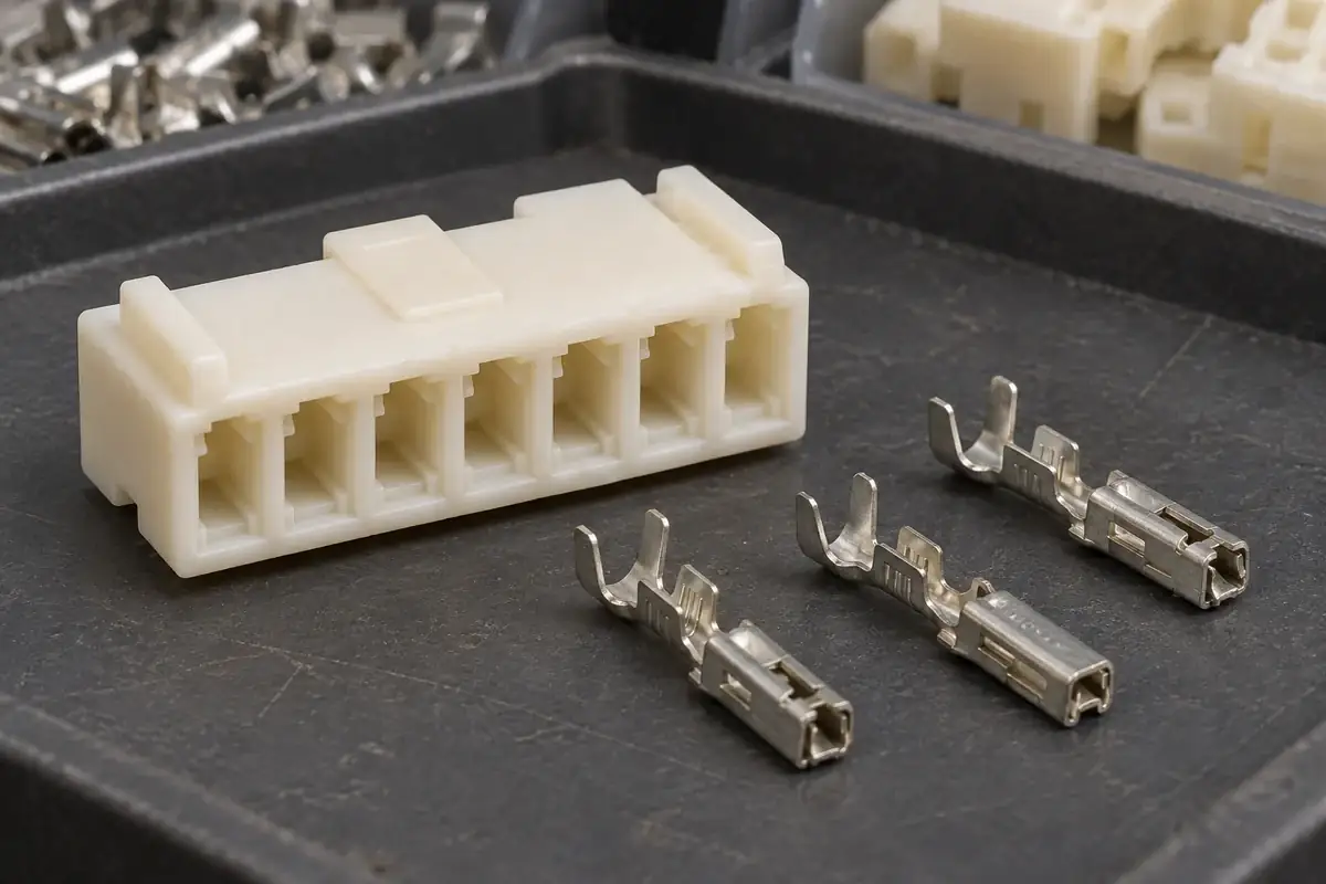
The wire-side housing and the board-side header are separate design objects. The housing locates the terminated wires, while the header connects to the board and provides the matching contact and guide arrangement. Calling both items a connector body can hide a responsibility gap when the plastic drawing is released without the current mating-header definition.
A straight header and a right-angle header may belong to the same product family, yet place the wire exit in different parts of the enclosure. Compare the assembled orientation in the actual equipment. Space above the board, the route toward the cable support and the direction of service removal can be more decisive than the height of an individual loose component.
TE's wire-to-board housing overview distinguishes housings, contacts, headers and optional locking parts within connector systems. Use that separation when organizing a custom program: it keeps a housing quotation attached to the intended interfaces without turning a component drawing into a claim of compatibility with an unrelated catalog part.
Write down which half establishes guidance before electrical engagement, which feature ends the insertion movement and where the retaining mechanism acts. These relationships determine the housing's functional surfaces. An overall width or nominal contact count does not reveal them, and a visually similar cavity arrangement does not resolve a mismatch in the mating sequence.
Choose locking around access and service conditions
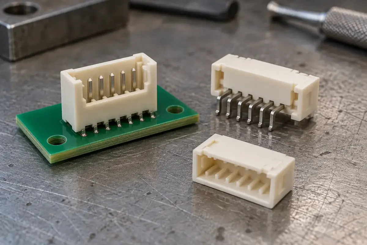
A friction-retained arrangement can offer a simple exterior and compact handling envelope. A positive latch introduces a defined release action and usually requires space for the latch to move. The relevant question is not which style is universally better, but whether the actual assembly and service operations can engage, confirm and release the chosen mechanism.
Molex's wire-to-board range includes friction-lock and other connector configurations. Their existence illustrates the range of system choices; the appropriate retention and qualification requirements still come from the application. Do not transfer a catalog family's performance to a custom housing because it uses a superficially similar latch.
Consider what happens after surrounding parts are installed. A latch visible on an open bench may sit under a bracket in the finished product. Adding a taller release tab can improve access but also create a snagging feature. A better arrangement may move the header, change the release direction or provide an enclosure opening that supports the intended service motion.
Harness routing belongs in this comparison. A tight wire bend immediately behind the housing can keep a steady side load on the assembly. That load is different from the deliberate axial withdrawal used to characterize a mating pair. The guide to wire-exit bend space explains why a larger latch alone may not solve a routing problem.
Review the configuration that will actually be built
Terminal selection should include the wire construction and its insulation size. Two wires described by the same conductor gauge can produce different crimp envelopes and bend behavior. Before changing the plastic cavity to accept an awkward assembly, compare the selected contact and wire combination using the approach in wire gauge versus insulation diameter.
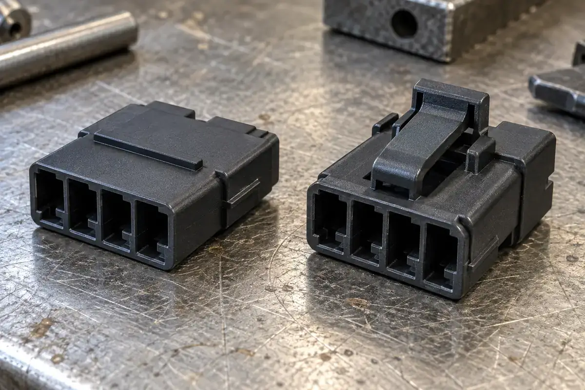
Then walk through the build order. Can each terminated wire be presented along the required insertion axis? Will the first populated cavities obstruct the remaining ones? If a rear cover or secondary lock is used, determine when it is installed and what must remain accessible until that stage. These questions often reveal missing component definitions before tooling starts.
Maintain one configuration reference for the housing, contact, wire, header and any accessory. A later change to a contact's crimp section can matter even if the mating contact tip remains unchanged. Likewise, replacing a board header with another mounting style can change the practical harness route without changing the electrical schematic or the number of circuits.
For custom wire-to-board connector housings, share the plastic model together with those counterpart drawings and the intended assembly sequence. That gives the molding review a concrete target: cavities, stops, guide surfaces and access features that serve a defined wire-to-board arrangement. The resulting quotation can then address the component you need and the checks that establish its mechanical fit.