
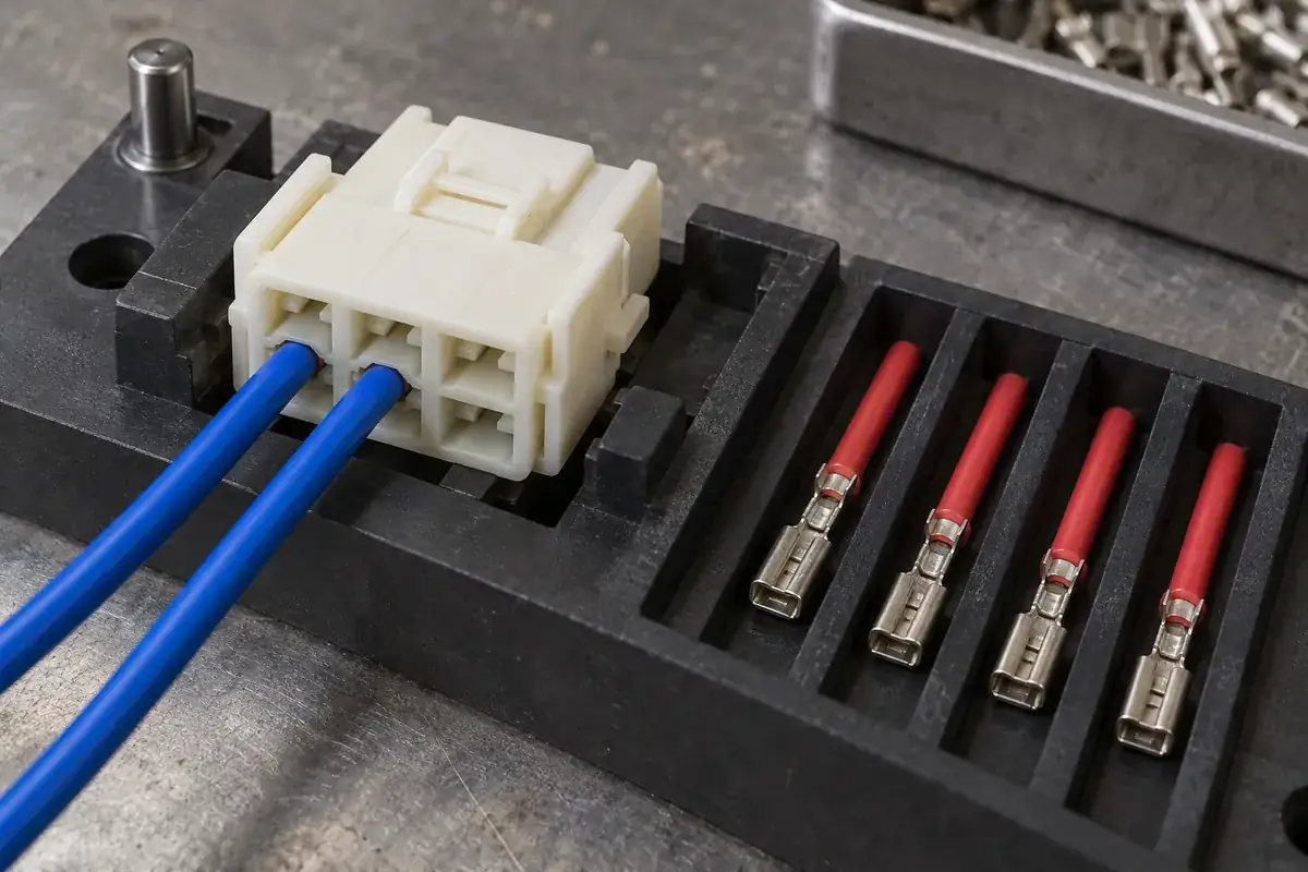
The first terminal slides into an empty housing without difficulty. By the time the last positions are reached, the earlier wires obscure the cavity entrances, cross the work area and make the correct orientation harder to judge. The problem may be described as a tight connector even though the same terminal fits easily when the housing is empty.
Sequential loading changes the working environment after every insertion. A useful assembly review therefore follows the housing from empty to fully populated, including the wires already installed. That approach can reveal whether the solution belongs in the loading order, the temporary wire supports or the plastic geometry.
Product design illustrations accompany the assembly and manufacturing explanations below.
Choose an orientation that stays meaningful throughout the build
Establish a stable housing orientation using physical features that remain visible as wires accumulate. A latch, keyed wall or fixture surface can provide a reference. If the assembly instruction uses a cavity diagram, state the viewing direction and keep that relationship consistent at the station. Flipping the housing halfway through without changing the reference can reverse the apparent wire order.
Numbering is useful only if it can still be read or otherwise confirmed at the relevant step. Small molded characters on the rear face may disappear behind the first row of wires. Consider how the circuit map is presented, where the fixture holds the housing and whether the instruction needs a separate reference for a second row.
Do not rely on wire color alone to maintain the sequence. Repeated colors, similar shades and variants with different circuit populations can defeat a visually convenient method. Use the controlled circuit identification and terminal orientation requirements with the production process selected for the harness.
Map how the available access changes
Try the proposed order with representative wire lengths, insulation diameters and crimp geometry. A narrow loose lead is not a substitute for the thickest approved wire configuration. The installed wires occupy volume, resist bending and may spring back into the next cavity's approach path.
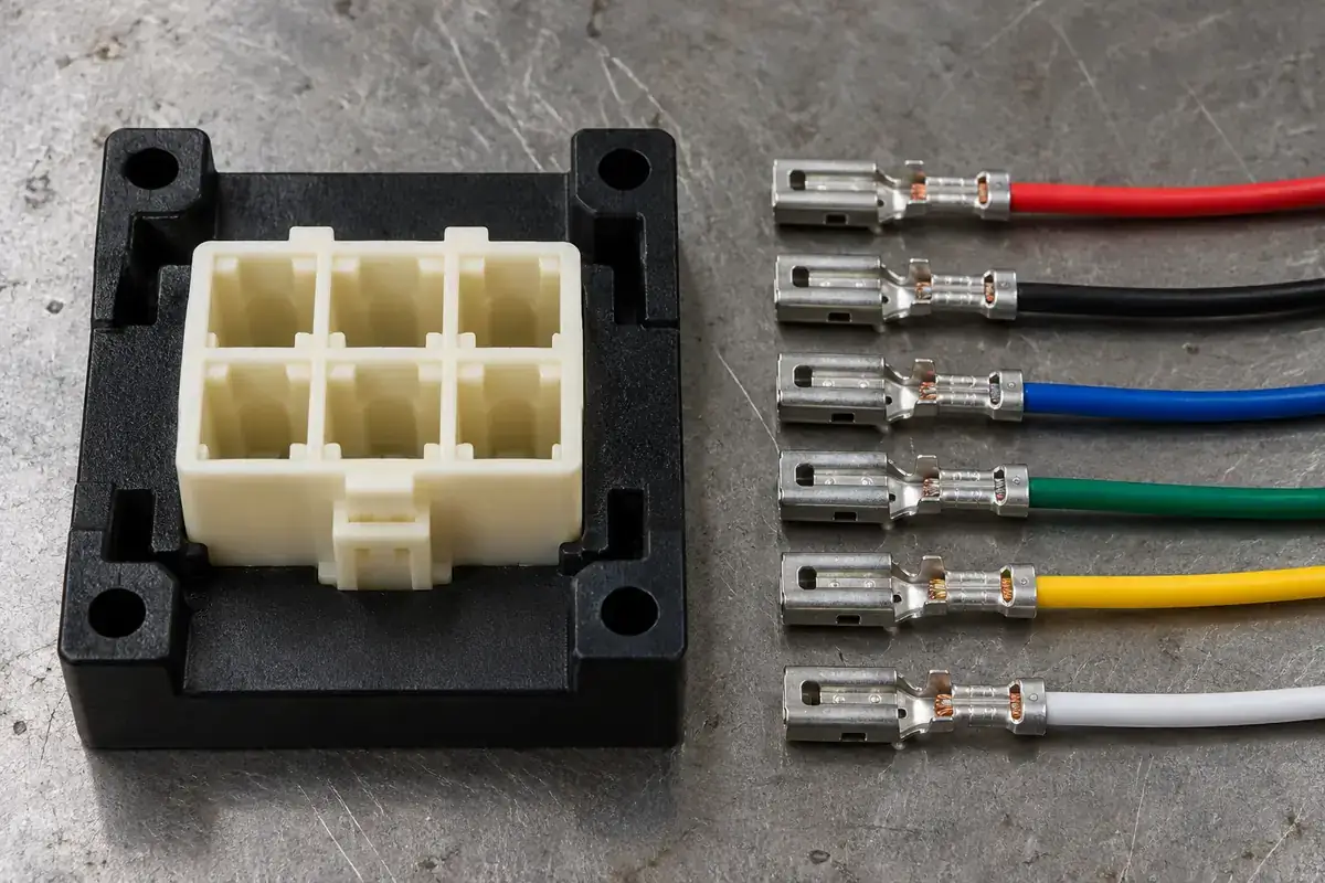
For a multi-row housing, loading a recessed or less accessible row first may preserve a straighter approach. In another geometry, a different order may be needed to maintain visibility or avoid crossing wires. There is no universal inside-out or outside-in sequence. Compare the alternatives against the actual rear opening and the harness branch directions.
Include any temporary supports in the review. A simple comb or separated tray channels can keep completed wires out of the active insertion path. The support should not pull an already loaded terminal backward or bend its crimp sharply. Its job is to manage access while leaving the terminal in the intended seated state.
Separate terminal preparation from insertion problems
A terminal with excessive crimp-envelope size or a damaged orientation feature can obstruct insertion even when access is clear. Check the prepared contact before blaming the loading order. Otherwise, a process change may merely make it easier to force a nonconforming terminal into the housing.
The approved insertion method belongs to the selected terminal system. Molex's application-tooling resources include terminal insertion and extraction guidance associated with its components. Use the relevant product instructions for a catalog terminal and define the corresponding method when developing a custom housing around it.
As the harness fills, operators may instinctively push on a wire at an angle because the terminal box is no longer easy to approach. That changes the force direction and can hide interference. Keep the approved insertion path accessible rather than compensating with more force. The article on crimp-terminal insertion interference examines the contact and cavity geometry separately.
Confirm each step before it becomes hidden
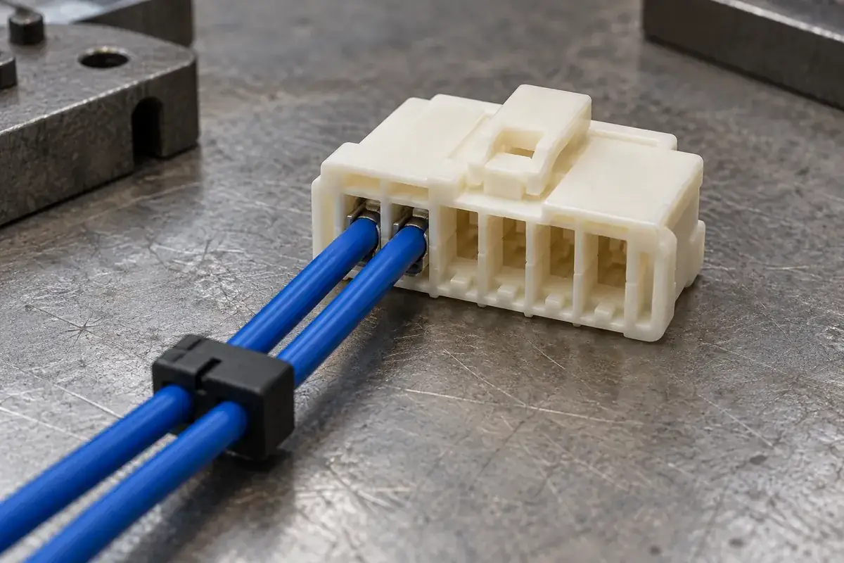
Decide when terminal seating can be assessed most effectively. Some features are easier to view immediately after insertion than after the next wire is installed. Others need a defined final inspection. Put the checks at stages where they can observe the intended condition instead of expecting a final overview to reveal every hidden interface.
Use only the seating confirmation appropriate to the terminal design and approved assembly process. An audible click may be difficult to distinguish in production, while a general tug can become uncontrolled if no method is defined. Mechanical position, circuit identity and electrical continuity answer different questions and should not be treated as interchangeable.
Secondary locks and rear covers can hide the rear entries. Their installation should follow the required contact checks and any correction work. If a lock is intended to detect an incompletely seated contact, evaluate that behavior as part of the design; do not assume every secondary lock provides the same error detection.
Make variants and repairs part of the sequence
A partly populated version needs its own agreed empty-position map. A loading instruction written for the full circuit count can encourage an operator to fill a cavity that should remain empty. Blockers, if used, also occupy working space and may need to be installed at a particular stage. See the separate guide to unused cavities and plugs.
Consider how one incorrect wire will be corrected after the other positions are loaded. The repair may require opening a cover, releasing a secondary lock or moving nearby wires. A housing that is straightforward to assemble but impossible to depin in its populated state creates unnecessary replacement work. Preserve the intended extraction path where service is required.
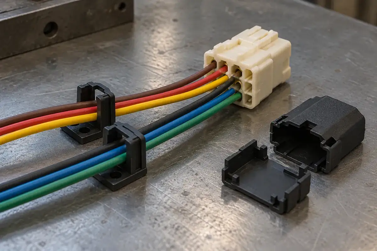
Record the tested assembly order, fixture orientation and confirmation points with the housing revision. If wire size, circuit population or cover geometry changes, revisit the relevant steps. A sequence that worked for the original harness may not transfer unchanged to its next variant.
For a new wire-to-board housing, supply a representative harness layout with the terminal drawings. Reviewing the partly assembled states can be as important as reviewing the final CAD assembly, because those states determine whether production can reach the intended result consistently.