
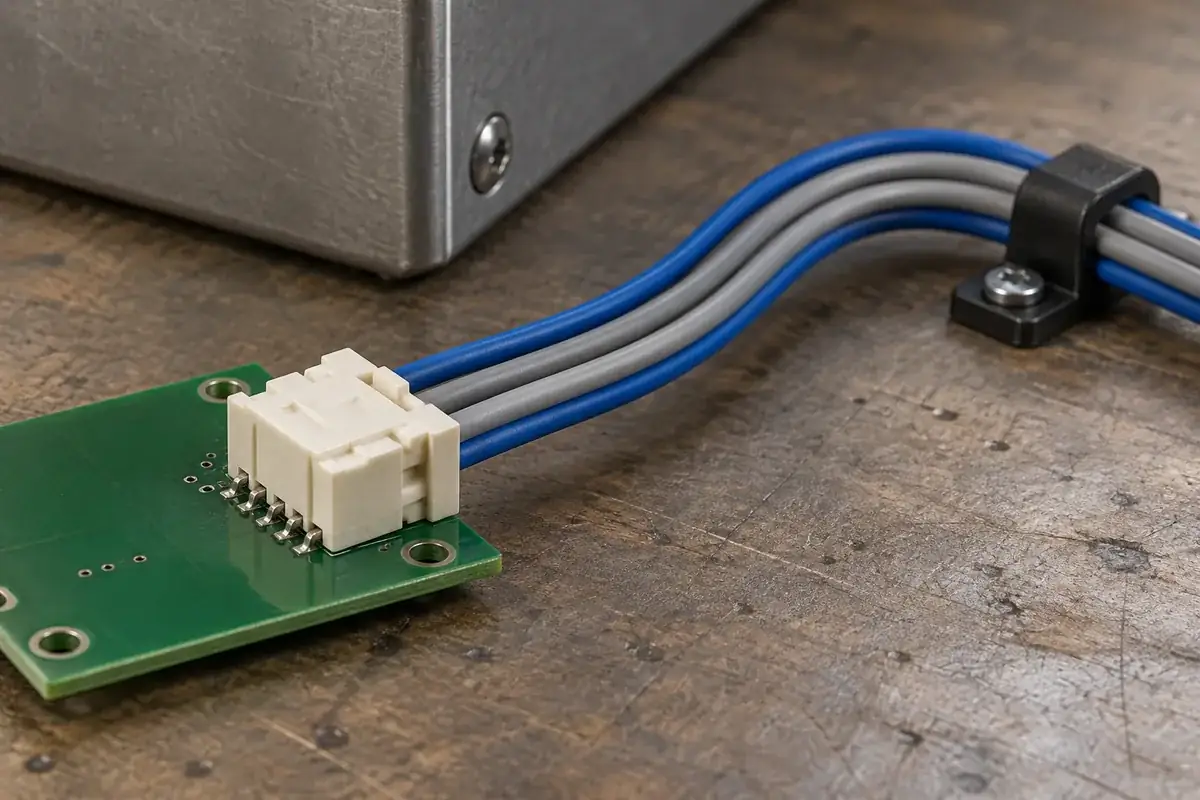
A wire-to-board connector can pass a bench fit check and become heavily loaded when the enclosure lid is installed. The lid pushes the harness sideways, the bundle turns immediately behind the housing, and the connector becomes the nearest support point. What looks like a weak latch may begin as an unresolved routing requirement outside the plastic part.
Exit-space planning asks where the wires are free to move, where the harness is restrained and which structure carries the resulting force. The answer involves the housing, wire construction, header orientation, enclosure and assembly sequence. It cannot be reduced to adding a generous curve to a CAD model without showing the actual support locations.
Product design illustrations accompany the assembly and manufacturing explanations below.
Follow the route from the contact outward
Start with the contact's approved termination and the rear of the housing. Determine which part of the wire is supported by the terminal or an accessory and where the free wire begins. An apparent gap behind the housing may already contain the insulation-support crimp or a required cover, leaving less usable routing length than the exterior model suggests.
Next identify the first restraint outside the connector. It might be a clip, a tie point, a channel or a rigid cable exit. The distance and direction between that restraint and the housing influence the load path. A support placed close to the connector can be helpful if aligned correctly, or harmful if it forces the bundle into a sharp sideways displacement.
Then include the rest of the equipment. A harness crossing a removable panel must move during service, while one trapped beneath a fixed bracket may need to be routed before the board is installed. These sequences affect available wire length and access. A tidy final arrangement is not enough if reaching that arrangement requires pulling against the contact termination.
Use the actual wire and bundle
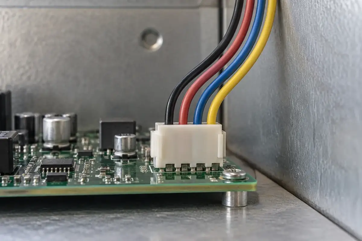
Wire diameter, insulation construction and flexibility influence the route. A thicker jacket changes both the occupied space and the way the wire responds to bending. The selected wire specification should supply the applicable handling and bend requirements. Avoid inventing a universal bend radius from conductor gauge or from a photograph of a similarly sized harness.
A group of wires is not always as flexible as one wire multiplied by its count. Tape, sleeving, twisting or a tie can make the bundle behave differently and move the point where individual wires can redistribute. Model the configuration that will be built, including where bundling begins and how the wires fan into the housing.
The JST handling precautions advise providing suitable wire allowance to avoid abnormal loading at connector joints. That principle is useful in layout review: the required allowance should be defined for the actual harness and operation, rather than borrowed as an arbitrary length from a different connector assembly.
Changing to another wire of the same gauge may alter the route even if the new wire still fits the contact. A stiffer or larger jacket can push against the enclosure or change the bundle's preferred direction. Review that mechanical effect alongside the cavity-fit questions in wire gauge versus insulation diameter.
Do not confuse routing force with connector retention
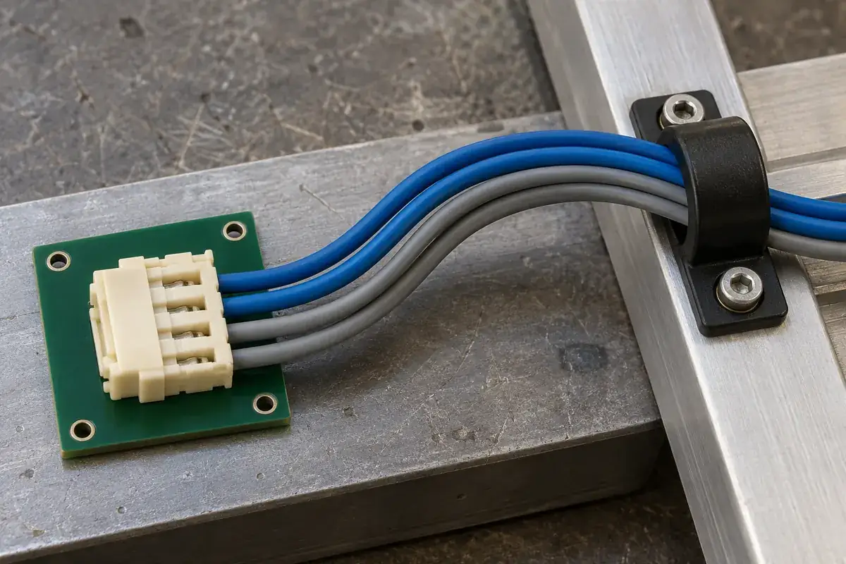
A retention requirement describes a particular mechanical relationship under specified conditions. A harness bent against an enclosure can apply a combination of side force and moment over time. Passing an axial test does not, by itself, establish that the assembly can accept that different loading condition. Identify the expected route and its restraint before assigning additional demands to the latch.
Look for the structural path through the board-side component as well. A load applied to the wire-side housing can reach the header, its board attachments and the PCB. Depending on the arrangement, those features may react the force before the plastic latch becomes the limiting element. Strengthening one small housing detail may leave the original equipment-level problem untouched.
Moving a clip or rotating a header can sometimes create a more direct route than increasing the size of the connector. Such changes have their own consequences for board area, assembly access and service. Compare them while the layout is still adjustable, and keep the chosen load path explicit so later packaging changes do not quietly reintroduce the conflict.
Check the route with the enclosure at its intended assembled condition. A lid, gasket or adjacent cable can occupy space that was empty during an open-bench inspection. Review both the nominal configuration and the relevant permitted variation. The useful evidence shows whether the harness is displaced by assembly, rather than merely confirming that the cover can be fastened.
Leave a route for assembly and service
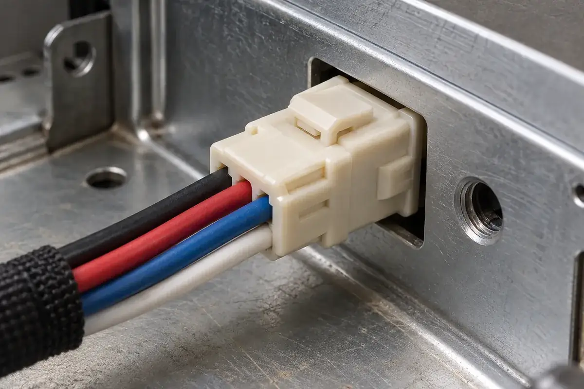
Latch access and wire routing should be evaluated together. A bundle placed over a release tab may prevent deliberate disconnection or cause someone to pull on the wires instead. Define the intended release motion and ensure that the final route leaves room for it. If a tool is required, its approach envelope also belongs in the equipment layout.
Service allowance must be purposeful. Excess wire can snag, rub against a sharp edge or become trapped under a fastener. Insufficient wire can prevent a board or panel from moving far enough to reach the release mechanism. Find the necessary movement for the defined service operation, then place the support and excess length where they can be controlled.
The choice of straight or right-angle header can change these constraints substantially. Compare the mated configuration and the direction in which it must be disconnected, not simply the connector's stated profile. The overview of wire-to-board housing types connects that mounting choice to the wider termination and assembly decisions.
For a custom wire-to-board housing review, provide a section of the equipment layout with the wire specification, first support point and service motion. Include any rear cover or strain-relief component. That lets the housing geometry be developed around a usable route and makes clear which loads the equipment supports instead of leaving them at the connector by accident.