
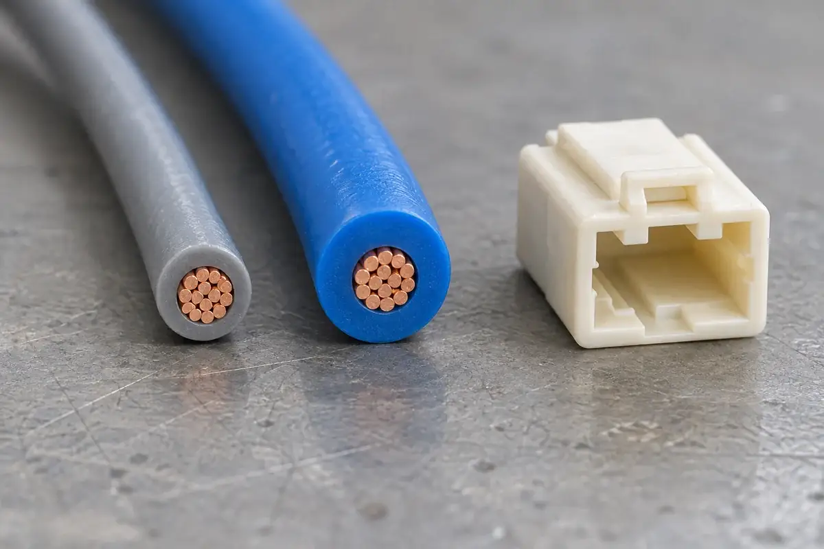
The replacement wire has the same AWG designation, the electrical drawing is unchanged, and the contact supplier still lists that conductor size. Yet the harness no longer loads smoothly into the plastic housing. The missing variable is often outside the conductor: insulation diameter, its stiffness, and the shape created when the terminal's support wings close around it.
AWG describes conductor size. It does not define the finished wire's complete mechanical envelope. When a connector housing receives a terminated wire, it encounters the contact, the conductor crimp, the insulation support and sometimes part of the jacket. A substitution must remain suitable for each interface, not merely preserve the nominal copper size on the bill of materials.
Product design illustrations accompany the assembly and manufacturing explanations below.
Separate the dimensions that belong to the wire
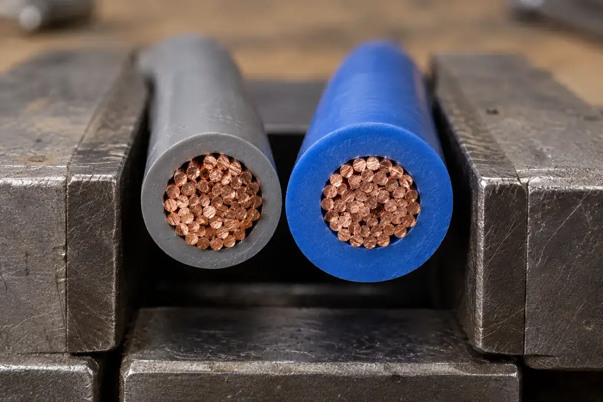
A wire specification can include conductor construction, insulation material, wall thickness and finished outside diameter. Stranding and compaction can also affect how the conductor presents to the crimp tooling. Two compliant wires of the same gauge may therefore have different jacket diameters and different responses when a support crimp compresses the insulation.
The outside diameter should be treated as a controlled range rather than a single attractive catalog number. Inspect representative material using the agreed method without flattening a soft jacket through excessive measuring force. For oval or irregular insulation, the direction of measurement matters. A reading taken at one angle can miss the envelope presented to a narrow rectangular entry.
Insulation stiffness adds another dimension to the problem. A flexible jacket may deform during entry while a harder jacket resists, even when their measured diameters are similar. Deformation is not automatically acceptable clearance. The design should establish what can pass without scraping, folding the support crimp or applying an uncontrolled load to the terminal's retaining features.
The terminal connects two different envelopes
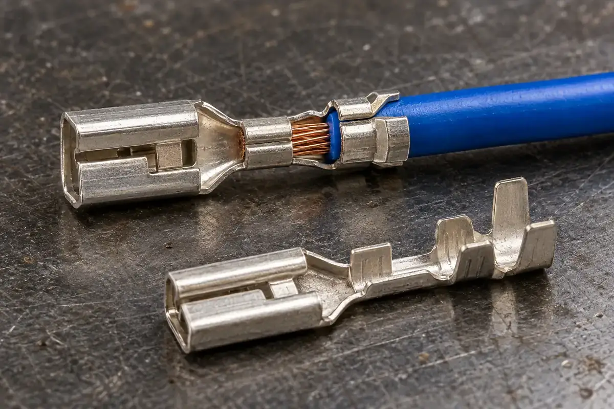
The conductor crimp and the insulation support have separate functions. The former establishes the specified conductor termination, while the latter supports the wire behind it according to the terminal design. A larger jacket may require a different support geometry even when the conductor crimp remains within the same nominal gauge range. Neither region should be adjusted by appearance alone.
The JST PH series data lists conductor size and insulation outside diameter separately for its contact options. That is a useful way to organize the review. The listed ranges are specific to those contacts; they are not general limits for a custom housing or permission to mix a different contact and wire construction.
Use the finished terminal envelope when assessing the housing. An uncrimped contact can slide through a cavity while the same contact, after termination to the selected wire, cannot. The insulation-support wings may become the widest region. Their position relative to the contact box also matters because the narrowest housing section may be encountered before the contact reaches its seated position.
A combination that looks tight is not necessarily corrected by opening the crimp. That can change the intended wire support and introduce movement farther along the termination. Similarly, increasing compression simply to make the package smaller may damage the insulation or alter the conductor termination. Resolve crimp settings with the approved application specification and tooling, then assess the resulting envelope.
Find where the housing actually restricts passage
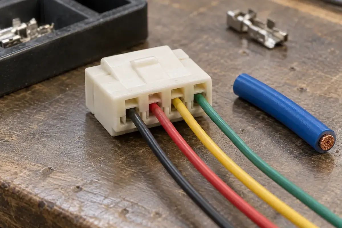
The rear opening is only the start of the insertion path. A cavity may narrow farther inside, contain a locating shoulder or include clearance for a retaining lance. Determine which part of the crimped assembly reaches each section. A large entrance chamfer does little when the interference occurs at an internal transition beyond the area that can be seen from outside.
Distinguish the space needed during travel from the space occupied after seating. Some housing designs leave the insulation support outside the main contact cavity. Others contain more of the terminated region. The correct arrangement comes from the defined contact and housing design, not a rule that all jacketed wire must enter or remain outside a connector body.
Rear covers and strain-relief accessories introduce further constraints. The housing can pass the terminal successfully while the assembled cover pinches the jacket or forces an immediate bend. Compare the cover in its final latched position, with the real number of wires and their diameter range, rather than checking one convenient sample through an open component.
If insertion has already become difficult, preserve the witness marks before trying repeated assembly. A polished spot on a support wing and a matching mark inside the entry can identify the contacting pair. The article on crimp-terminal insertion interference develops that diagnosis without assuming that every tight assembly is a molding defect.
Approve wire changes with the assembly in view
Begin a substitution review with the old and proposed wire specifications, the contact reference and the applicable crimp definition. Record what changes in conductor construction, insulation diameter and jacket material. This creates a traceable mechanical comparison and avoids reducing several simultaneous changes to the statement that both wires have the same gauge.
Compare representative terminated samples before modifying the housing tool. Establish the relevant width, height and alignment of the formed metal regions using the contact supplier's method. A terminal bent during handling can exaggerate a clearance concern. Keeping that condition separate from the normal crimp envelope makes the resulting tooling decision more reliable.
Next examine the populated harness in its equipment route. A wire that fits the cavity may be too stiff for the available exit path, particularly when several wires are gathered into a bundle. Review the support and free length described in harness bend-space planning, because moving the problem beyond the housing entrance does not eliminate it.
For a new wire-to-board housing molding project, provide the wire's mechanical specification as well as its gauge. Include the selected terminal and the required finished termination condition. Those inputs allow the rear-entry geometry, cavity transitions and accessory clearances to be reviewed against a real assembly, with changes directed at the interface that actually needs them.